Winding overhang support of an electrical machine

A technology for winding ends and supporting devices, applied in the directions of electromechanical devices, windings, electric components, etc., can solve problems such as cooling interference, and achieve the effect of improving cooling

Active Publication Date: 2012-08-01
ANDRITZ HYDRO GMBH
View PDF5 Cites 1 Cited by
  • Summary
  • Abstract
  • Description
  • Claims
  • Application Information

AI Technical Summary

Problems solved by technology

In the case of such an arrangement, especially in the case of electric machines in the high power range, it is problematic that the ventilation slits arranged between the partial lamination packs pass through for cooling the rotor. The rotor sleeve shrunk onto the rotor body is closed, so that the cooling of the rotor body is disturbed in this region

Method used


Image

  • Winding overhang support of an electrical machine
  • Winding overhang support of an electrical machine
  • Winding overhang support of an electrical machine

Examples


Embodiment Construction

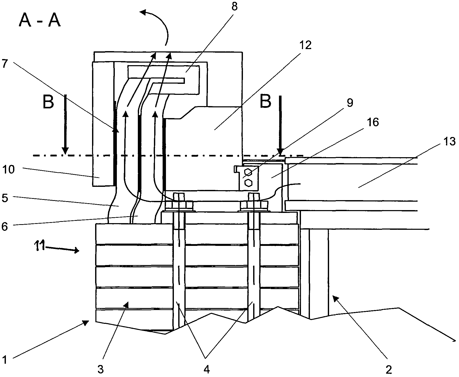
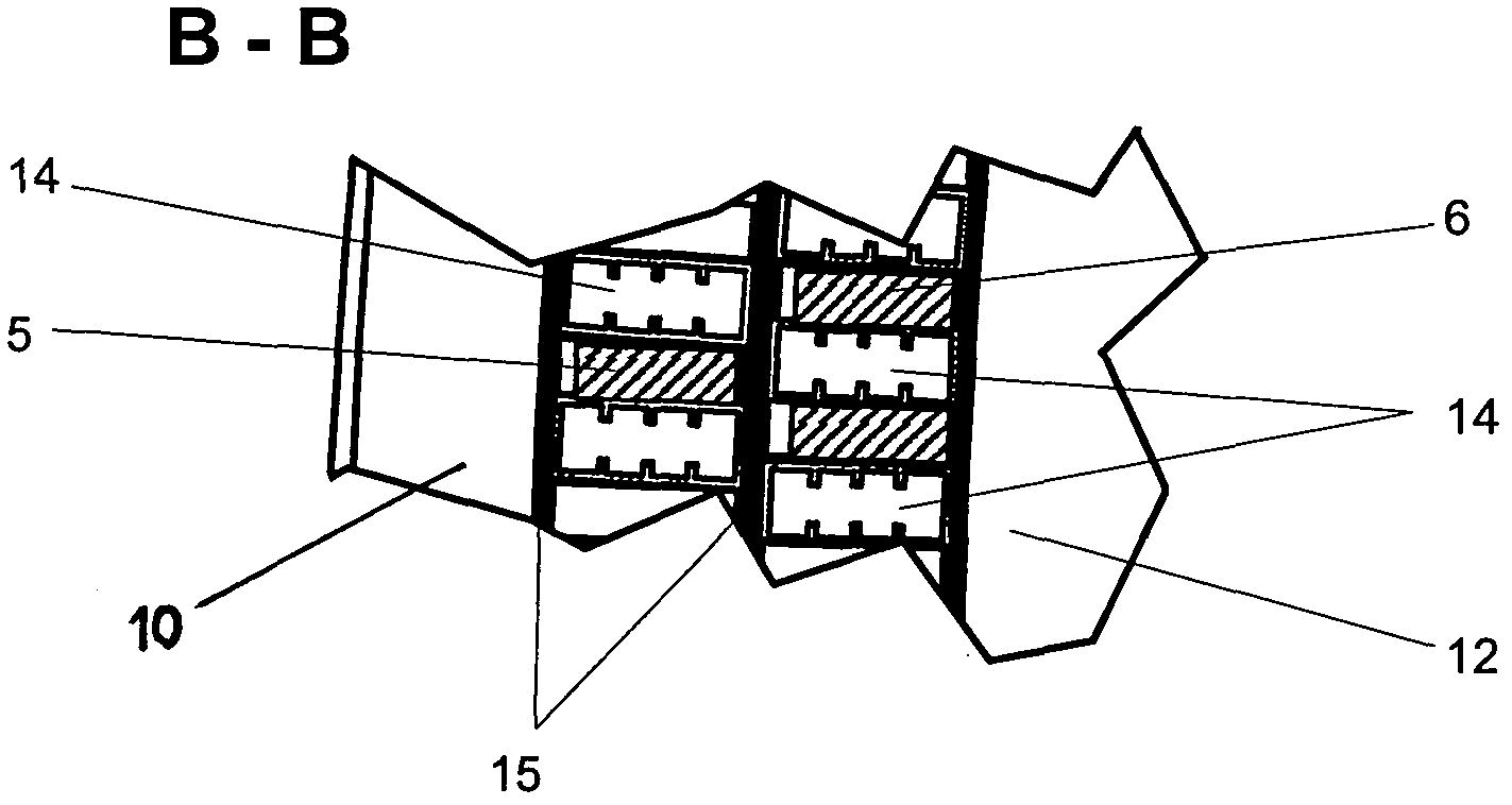
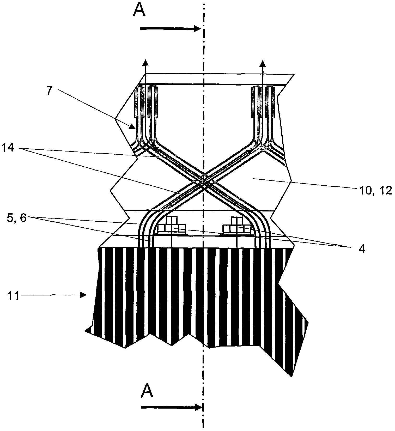
[0028] Motors such as hydroelectric generators are figure 1 The rotor 1 shown in FIG. 2 comprises spokes 2 on which a laminated core 3 of the rotor 1 is arranged in a known manner. In this case, the laminated core 3 is held together by well-known hold-down screws 4 . In this case, the spokes 2 and the laminated core 3 form the rotor body 11 of the rotor 1 . Slots are arranged in the radially outer region of the laminated core 3 , not shown here, into which slots the insulated winding bars (here upper bar 5 and lower bar 6 ) are inserted and held radially by means of slot wedges. . Such arrangements are sufficiently known and therefore not discussed further here. The winding bars 5 , 6 protrude axially from the laminated core 3 on both sides and form so-called winding ends 7 outside the laminated core 3 . As is well known, the winding bars 5 , 6 are arranged obliquely relative to the axial direction in the region of the winding head 7 , wherein the upper bar 5 and the lowe...


PUM


Abstract

The winding overhang of the rotor of an electrical machine is subject to strong centrifugal forces during operation, especially when the machines run at high speed. The aim of the invention is therefore to devise a winding overhang support which prevents the production of relative movements between the winding overhang and the rotor base, said relative movements resulting in strong mechanical stresses on the winding bars. The invention relates to a winding overhang support which consists of an inner ring (12) and an outer ring (10) between which the winding bars (5, 6) are arranged in the region of the winding overhang (7), the outer ring (10) being shrunk on the inner ring (12) and both the outer ring (10) and the inner ring (12) being interspaced from the lamination stack (3).

Description

technical field [0001] A representative invention relates to a support device for the winding ends of a rotor of an electrical machine, wherein the rotor comprises a lamination stack, wherein a plurality of winding bars are arranged distributed over the periphery of the lamination stack, wherein the winding bars extend beyond The axial end of the lamination stack to form the winding end and relates to a method for assembling a rotor winding with such a winding end support. Background technique [0002] If the rotor of the electric machine has bar windings, the winding bars are often subjected to high centrifugal forces, especially at high rotational speeds. For example, the rotor windings of machines with variable speed are often embodied as bar windings. In particular, the machines of variable-speed pumped-storage power plants are operated at high speeds and the rod coils of these machines are therefore subjected to high centripetal accelerations. In the region of the rot...

Claims


Application Information

Patent Timeline
Patent Type & Authority Applications(China)
IPC IPC(8): H02K3/51H02K3/52H02K3/24H02K3/12
CPCH02K3/24H02K3/51H02K3/12H02K3/527Y10T29/49012
Inventor 阿尔弗雷德·莱克塞尔斯特凡·黑尔姆林格
Owner ANDRITZ HYDRO GMBH
Why Eureka
Try Eureka