Turbine blade capable of retarding cooling effect degradation by regulating and controlling internal dust deposition position
A technology for turbine blades and cooling effects, applied in the direction of blade support elements, engine components, machines/engines, etc., can solve problems that affect the heat exchange capacity and cooling effect of blades, do not inhibit internal dust deposition, and weaken the effect of impact cooling, etc. , to achieve the effect of slowing down the degradation of the cooling effect, keeping the effect unaffected, and ensuring the heat exchange capacity
- Summary
- Abstract
- Description
- Claims
- Application Information
AI Technical Summary
Problems solved by technology
Method used
Image
Examples
Embodiment 1
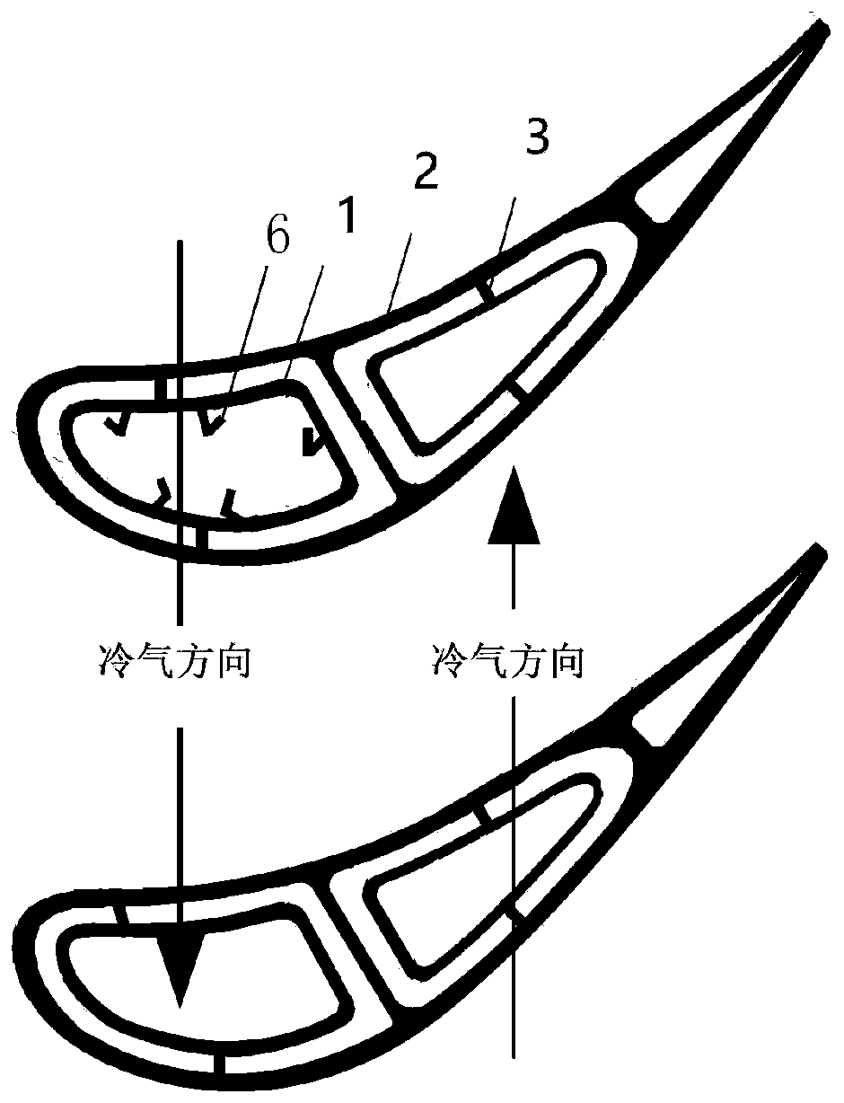
[0029] The turbine blade that slows down the degradation of the cooling effect by adjusting the internal dust deposition position, the turbine blade is a double-wall structure, specifically including the inner wall 1, the outer wall 2 and the spoiler column 3, the spoiler column 3 is located between the inner wall 1 and the outer wall 2, and the outer wall 2 The air film hole 4 is arranged on the inner wall 1, the jet hole 5 is arranged on the inner wall 1, and the shielding structure 6 is connected on the inner wall 1, and the shielding structure 6 is located upstream of the jet hole 5, such as figure 2 , image 3 and Figure 7 shown;
[0030] The height of inner wall 1 is 1mm, the diameter of jet hole 5 is 1mm, the height of outer wall 2 is 1mm, the distance between inner wall 1 and outer wall 2 is 1mm; the diameter of air film hole 4 is 0.4mm, the horizontal distance between the center of air film hole 4 and the center of jet hole 5 is 8mm, and the vertical distance 8mm;...
Embodiment 2
[0033] The turbine blade that slows down the degradation of the cooling effect by adjusting the internal dust deposition position, the turbine blade is a double-wall structure, specifically including the inner wall 1, the outer wall 2 and the spoiler column 3, the spoiler column 3 is located between the inner wall 1 and the outer wall 2, and the outer wall 2 The air film hole 4 is arranged on the inner wall 1, the jet hole 5 is arranged on the inner wall 1, and the shielding structure 6 is connected on the inner wall 1, and the shielding structure 6 is located upstream of the jet hole 5, such as Figure 4 and Figure 7 shown;
[0034] The height of inner wall 1 is 1mm, the diameter of jet hole 5 is 1mm, the height of outer wall 2 is 1mm, the distance between inner wall 1 and outer wall 2 is 1mm; the diameter of air film hole 4 is 0.4mm, the horizontal distance between the center of air film hole 4 and the center of jet hole 5 is 8mm, and the vertical distance 8mm; the diamete...
Embodiment 3
[0037] The turbine blade that slows down the degradation of the cooling effect by adjusting the internal dust deposition position, the turbine blade is a double-wall structure, specifically including the inner wall 1, the outer wall 2 and the spoiler column 3, the spoiler column 3 is located between the inner wall 1 and the outer wall 2, and the outer wall 2 The air film hole 4 is arranged on the inner wall 1, the jet hole 5 is arranged on the inner wall 1, and the shielding structure 6 is connected on the inner wall 1, and the shielding structure 6 is located upstream of the jet hole 5, such as Figure 5 and Figure 7 shown;
[0038] The height of inner wall 1 is 1mm, the diameter of jet hole 5 is 1mm, the height of outer wall 2 is 1mm, the distance between inner wall 1 and outer wall 2 is 1mm, and the diameter of air film hole 4 is 0.4mm; the horizontal distance between the center of air film hole 4 and the center of jet hole 5 is 8mm, and the vertical distance 8mm; the dia...
PUM
 Abstract
Description
Claims
Application Information
 - R&D
- Intellectual Property
- Life Sciences
- Materials
- Tech Scout
- Unparalleled Data Quality
- Higher Quality Content
- 60% Fewer Hallucinations
Browse by: Latest US Patents, China's latest patents, Technical Efficacy Thesaurus, Application Domain, Technology Topic, Popular Technical Reports.
© 2025 PatSnap. All rights reserved.Legal|Privacy policy|Modern Slavery Act Transparency Statement|Sitemap|About US| Contact US: help@patsnap.com


