Turbine blades that reduce cooling degradation by regulating the location of internal dust deposits

A technology for turbine blades and cooling effects, which is applied in the direction of supporting components of blades, machines/engines, mechanical equipment, etc., which can solve the problems of affecting the heat transfer capacity and cooling effect of blades, not inhibiting internal dust deposition, and weakening the effect of impact cooling, etc. , to achieve the effects of slowing down the cooling effect, smooth outflow, and ensuring heat exchange capacity

Active Publication Date: 2022-03-01
SHENYANG AEROSPACE UNIVERSITY
View PDF0 Cites 1 Cited by
  • Summary
  • Abstract
  • Description
  • Claims
  • Application Information

AI Technical Summary

Problems solved by technology

[0003] When the aircraft takes off, lands or passes through the volcanic ash cloud, the engine will inevitably inhale dust, and the cooling air with dust enters the double-wall structure through the jet hole, and the dust will form deposits inside the double-wall structure. The conductivity is relatively small, which is equivalent to adding a large thermal resistance during the heat transfer process, which seriously affects the heat transfer capacity and cooling effect of the blade
Especially the deposition on the impact target surface greatly weakens the effect of impact cooling, resulting in attenuation of cooling performance of blades
[0004] The current turbine blades have no effective measures to suppress internal dust deposition, and the problem of dust deposition has become increasingly prominent. Solving the problem of dust deposition inside the blades is crucial to the stable operation of high-performance gas turbines

Method used


Image

  • Turbine blades that reduce cooling degradation by regulating the location of internal dust deposits
  • Turbine blades that reduce cooling degradation by regulating the location of internal dust deposits
  • Turbine blades that reduce cooling degradation by regulating the location of internal dust deposits

Examples


Embodiment 1

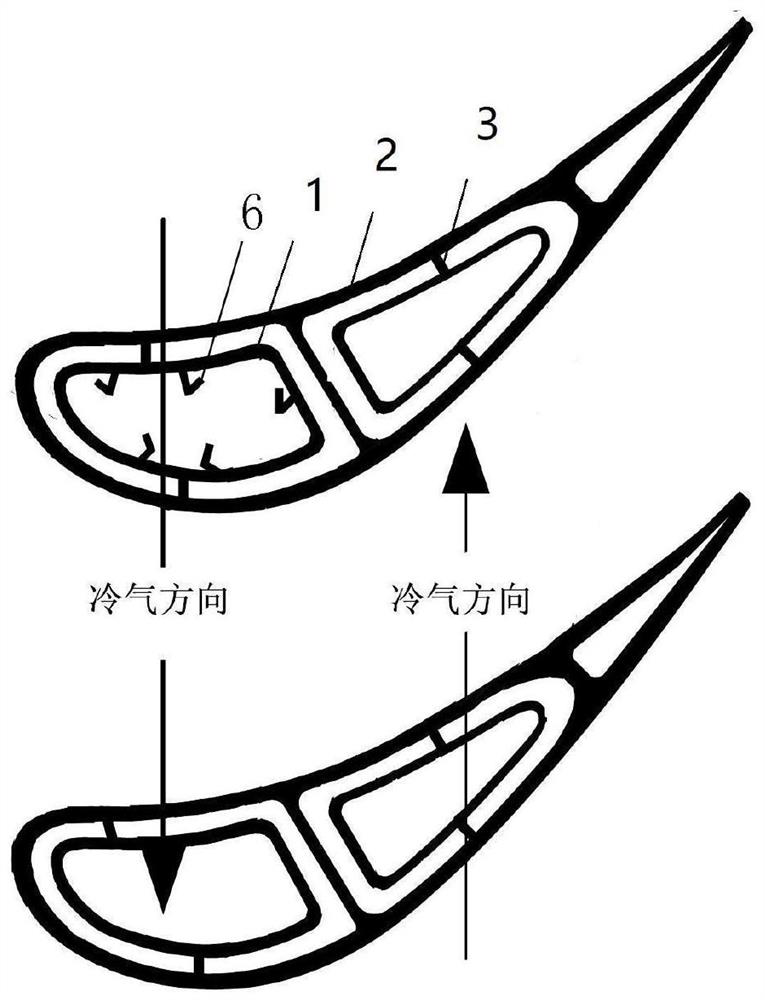
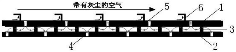
[0029] The turbine blade that slows down the degradation of the cooling effect by adjusting the internal dust deposition position, the turbine blade is a double-wall structure, specifically including the inner wall 1, the outer wall 2 and the spoiler column 3, the spoiler column 3 is located between the inner wall 1 and the outer wall 2, and the outer wall 2 The air film hole 4 is arranged on the inner wall 1, the jet hole 5 is arranged on the inner wall 1, and the shielding structure 6 is connected on the inner wall 1, and the shielding structure 6 is located upstream of the jet hole 5, such as figure 2 , image 3 and Figure 7 shown;

[0030] The height of inner wall 1 is 1mm, the diameter of jet hole 5 is 1mm, the height of outer wall 2 is 1mm, the distance between inner wall 1 and outer wall 2 is 1mm; the diameter of air film hole 4 is 0.4mm, the horizontal distance between the center of air film hole 4 and the center of jet hole 5 is 8mm, and the vertical distance 8mm;...

Embodiment 2

[0033] The turbine blade that slows down the degradation of the cooling effect by adjusting the internal dust deposition position, the turbine blade is a double-wall structure, specifically including the inner wall 1, the outer wall 2 and the spoiler column 3, the spoiler column 3 is located between the inner wall 1 and the outer wall 2, and the outer wall 2 The air film hole 4 is arranged on the inner wall 1, the jet hole 5 is arranged on the inner wall 1, and the shielding structure 6 is connected on the inner wall 1, and the shielding structure 6 is located upstream of the jet hole 5, such as Figure 4 and Figure 7 shown;

[0034] The height of inner wall 1 is 1mm, the diameter of jet hole 5 is 1mm, the height of outer wall 2 is 1mm, the distance between inner wall 1 and outer wall 2 is 1mm; the diameter of air film hole 4 is 0.4mm, the horizontal distance between the center of air film hole 4 and the center of jet hole 5 is 8mm, and the vertical distance 8mm; the diamete...

Embodiment 3

[0037] The turbine blade that slows down the degradation of the cooling effect by adjusting the internal dust deposition position, the turbine blade is a double-wall structure, specifically including the inner wall 1, the outer wall 2 and the spoiler column 3, the spoiler column 3 is located between the inner wall 1 and the outer wall 2, and the outer wall 2 The air film hole 4 is arranged on the inner wall 1, the jet hole 5 is arranged on the inner wall 1, and the shielding structure 6 is connected on the inner wall 1, and the shielding structure 6 is located upstream of the jet hole 5, such as Figure 5 and Figure 7 shown;

[0038] The height of inner wall 1 is 1mm, the diameter of jet hole 5 is 1mm, the height of outer wall 2 is 1mm, the distance between inner wall 1 and outer wall 2 is 1mm, and the diameter of air film hole 4 is 0.4mm; the horizontal distance between the center of air film hole 4 and the center of jet hole 5 is 8mm, and the vertical distance 8mm; the dia...


PUM


Abstract

The invention relates to a turbine blade which slows down the degradation of cooling effect by regulating the internal dust deposition position, and belongs to the technical field of gas turbines. The turbine blade has a double-wall structure, and a shielding structure is connected to the inner wall of the existing double-wall. The turbine blade of the present invention regulates the internal dust deposition position through the shielding structure to slow down the degradation of the cooling effect of the turbine blade, and the dust deposited on the double wall can be reduced by 10% to 13%, thereby slowing down the cooling effect of the blade by 20% to 23%. The degradation time is relatively simple, and the shape of the shielding structure is relatively simple, easy to process, and strong in realizability.

Description

technical field [0001] The invention belongs to the technical field of gas turbines, and in particular relates to a turbine blade which slows down the degradation of cooling effect by regulating the internal dust deposition position. Background technique [0002] With the development of gas turbine technology, the temperature in front of the turbine is further increased, which puts forward higher requirements for the cooling of turbine blades. At present, in the prior art, the cooling methods inside the blade mainly include convection cooling and impingement cooling, among which impingement cooling is the most effective method to enhance the local cooling effect. Impingement cooling mainly uses high-speed airflow to scour the surface to be cooled to achieve the purpose of cooling. The cooling air enters the double-walled structure with spoiler columns through the jet hole, and the airflow direction is as follows: figure 1 As shown, impact the surface to be cooled to achieve...

Claims


Application Information

Patent Timeline
Patent Type & Authority Patents(China)
IPC IPC(8): F01D5/14F01D5/18
CPCF01D5/147F01D5/18
Inventor 李广超王裕东张魏赵长宇曾睿寇志海朱建勇毛晓东
Owner SHENYANG AEROSPACE UNIVERSITY
Why Eureka
Try Eureka