Cement kiln system capable of realizing zero emission of carbon dioxide and cement clinker preparation method

A carbon dioxide and cement kiln technology, applied in the treatment of discharged materials, cement production, carbon capture, etc., can solve the problems of low concentration, high system investment and operation cost, low gas capture efficiency, etc. low cost effect

Active Publication Date: 2021-02-05
TIANJIN CEMENT IND DESIGN & RES INST
View PDF3 Cites 8 Cited by
  • Summary
  • Abstract
  • Description
  • Claims
  • Application Information

AI Technical Summary

Problems solved by technology

[0009] In order to overcome the defects of the prior art, the present invention provides a cement kiln system and a method for preparing cement clinker to realize zero emission of carbon dioxide, so as to solve the problem of capturing CO after com

Method used


Image

  • Cement kiln system capable of realizing zero emission of carbon dioxide and cement clinker preparation method
  • Cement kiln system capable of realizing zero emission of carbon dioxide and cement clinker preparation method
  • Cement kiln system capable of realizing zero emission of carbon dioxide and cement clinker preparation method

Examples


Embodiment 1

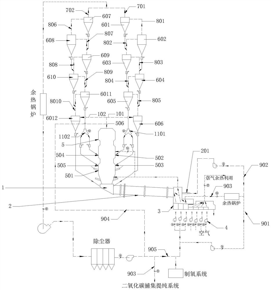
[0061] Such as figure 1 As shown, the cement kiln system for realizing zero emission of carbon dioxide in this embodiment includes a smoke chamber 1, a rotary kiln 2, a cooling machine 3, a fan 4, a raw material preheating and pre-decomposition system, a first pipeline assembly and a second pipe Road components, raw meal preheating and pre-decomposition system is a conventional raw meal preheating and pre-decomposition system.

[0062] The raw material preheating and pre-decomposition system is connected with the smoke chamber 1, the first burner 201 is installed on the rotary kiln 2, the tail of the rotary kiln 2 is connected with the smoke chamber 1, and the head of the rotary kiln 2 is connected with the cooler 1.

[0063] The raw material preheating and pre-decomposing system includes a calciner 5 and a cyclone preheater. The cyclone preheater includes a first row of cyclone preheaters and a second row of cyclone preheaters. It should be noted that the row of cyclone prehe...

Embodiment 2

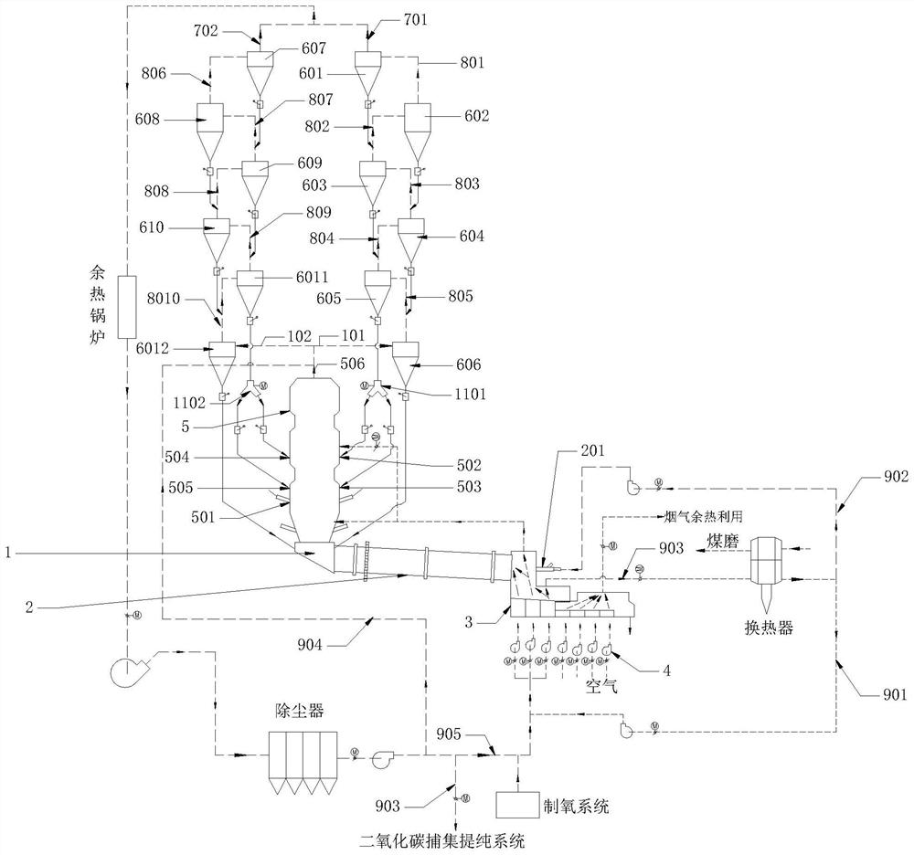
[0109] Such as figure 2 As shown, it is the cement kiln system of this embodiment to achieve zero emission of carbon dioxide, which is basically similar in structure to the cement kiln system of Embodiment 1, the difference is that the first waste heat utilization system of this embodiment includes a heat exchanger and a coal grinding device , that is, the first cooling gas in the third path exchanges heat with the air through the heat exchanger, and the air after heat exchange enters the coal mill for drying, and then is discharged into the atmosphere after being treated with flue gas. The gas after heat exchange is divided into The two paths enter the first branch pipeline 901 and the second branch pipeline 902 respectively.

[0110] The method for preparing cement clinker using the cement kiln system in this embodiment is the same as that in Embodiment 1.

Embodiment 3

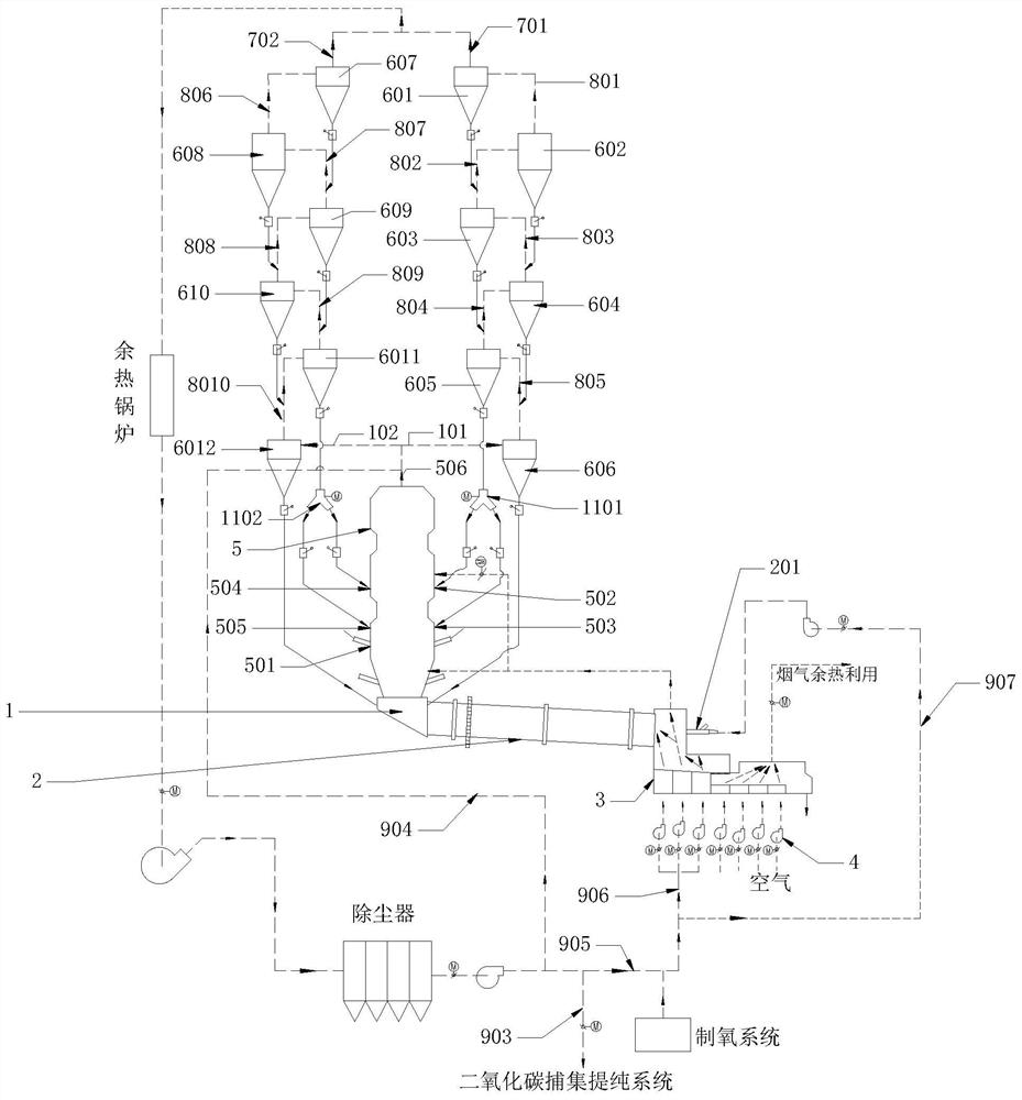
[0112] Such as image 3 As shown, the cement kiln system for realizing zero emission of carbon dioxide in this embodiment is basically similar to the structure of the cement kiln system in Embodiment 1, and the differences are as follows:

[0113] 1. The tolerance temperature of the middle roller breaker in the cooling machine 3 is ≥900°C, and the tolerance temperature of the middle roller breaker is ≥900°C. The roll breaker is generally located in the front section or the front middle section of the cooling machine 3. At this time, the first cooling gas is divided into Two way;

[0114] The first cooling gas from the first channel directly enters the rotary kiln as the secondary air for fuel combustion;

[0115] The first cooling gas of the second path enters the calciner as the tertiary air through the tertiary air duct for fuel combustion.

[0116]2. The other end of the fifth branch pipeline 905 is mixed with pure oxygen to obtain the mixed gas of pure oxygen and high-co...


PUM


Abstract

The invention provides a cement kiln system capable of realizing zero emission of carbon dioxide and a cement clinker preparation method. The system comprises a raw material preheating and pre-decomposing system, a smoke chamber, a rotary kiln and a cooling machine, wherein the smoke chamber, the rotary kiln and the cooling machine are sequentially communicated; the raw material preheating and pre-decomposing system comprises a decomposing furnace and a cyclone preheater, an air inlet of the cyclone preheater at the bottom end is connected with an air outlet pipe of the decomposing furnace, and low-temperature flue gas is exhausted from an air outlet of the cyclone preheater at the top end; a discharge port of the bottom end cyclone preheater is communicated with the smoke chamber, and a feed port of the top end cyclone preheater is used for feeding raw materials; the cooling machine comprises a first cooling area and a second cooling area, mixed gas of pure oxygen and high-concentration carbon dioxide flue gas is introduced into an air inlet of the first cooling area, and air is introduced into an air inlet of the second cooling area. The problems of low CO2 gas capture efficiencyof a CO2 capture and purification system, low CO2 concentration in flue gas entering the capture and purification system and high system investment and operation cost in the existing CO2 capture technology after combustion can be solved.

Description

technical field [0001] The invention belongs to the technical field of cement production equipment, and in particular relates to a cement kiln system and a cement clinker preparation method for realizing zero emission of carbon dioxide. Background technique [0002] CO 2 As a major greenhouse gas, its massive emissions have exacerbated the global greenhouse effect. All countries in the world are generally faced with the arduous task of reducing carbon emissions and mitigating global climate change. In order to better develop the global economy and protect the natural environment, countries around the world have successively formulated strategic goals for carbon emission reduction. In my country, the cement industry has become the second largest CO after the power industry. 2 Emission source. According to statistics, the national output of cement clinker in 2018 was about 1.42 billion tons, and the CO 2 Under the technical level condition with emission of about 0.84 tons,...

Claims


Application Information

Patent Timeline
IPC IPC(8): C04B7/44C04B7/47F27B7/34F27B7/36F27B7/38F27D15/02F27D17/00
CPCC04B7/44C04B7/47C04B7/4476F27B7/34F27B7/36F27B7/38F27D15/02F27D17/004Y02P40/18
Inventor 代中元胡芝娟彭学平陈昌华赵亮
Owner TIANJIN CEMENT IND DESIGN & RES INST
Why Eureka
Try Eureka