Automatic control oil tank

A fuel tank and control system technology, applied in the field of automatic control of fuel tanks, can solve the problem of low accuracy of calculation results of oil consumption, achieve the effect of reducing labor intensity and avoiding potential safety hazards

Active Publication Date: 2015-01-21
CHINA HANGFA SOUTH IND CO LTD
View PDF10 Cites 0 Cited by
  • Summary
  • Abstract
  • Description
  • Claims
  • Application Information

AI Technical Summary

Problems solved by technology

[0003] The purpose of the present invention is to provide an automatic control oil tank to solve the technical problem that the calculation result of oil consumption is not accurate

Method used


Image

  • Automatic control oil tank
  • Automatic control oil tank

Examples


Embodiment Construction

[0026] The embodiments of the present invention will be described in detail below with reference to the accompanying drawings, but the present invention can be implemented in many different ways defined and covered by the claims.

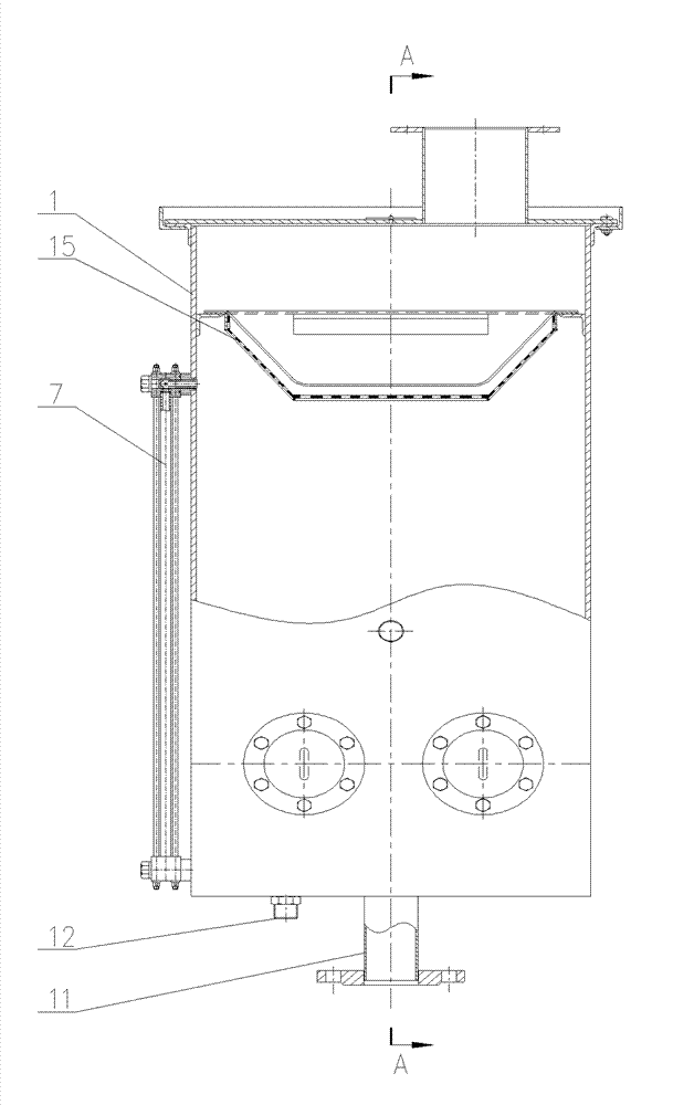
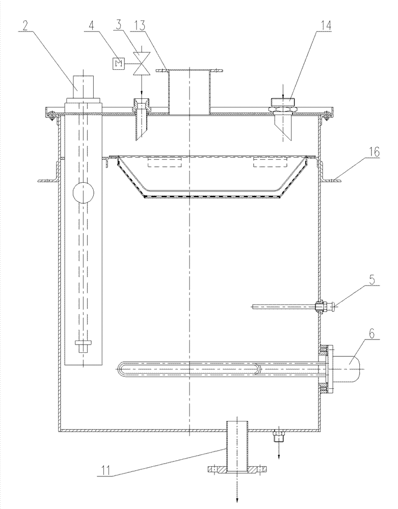
[0027] see in conjunction figure 1 and figure 2 The automatic control oil tank of the present invention includes a fuel tank body 1, a liquid level sensor 2 axially installed in the oil tank body 1 and a control system (not shown) connected to the liquid level sensor 2.

[0028] The oil tank body 1 is used to accommodate oil, and the bottom of the oil tank body 1 is provided with an oil delivery interface 11, and the oil tank body 1 delivers oil to the equipment to be tested through the oil delivery interface 11. In order to accurately measure the oil consumed by the test equipment, the liquid level sensor 2 senses the liquid level of the oil in the oil tank body 1 to obtain a liquid level signal, and sends the liquid level signal to the control s...


PUM


Abstract

The invention provides an automatic control oil tank, which comprises an oil tank body accommodating oil, and the oil tank body conveys the oil to a device to be tested through an oil-conveying port. The automatic control oil tank further comprises a liquid level sensor and a control system, wherein the liquid level sensor is axially installed in the oil tank body, is electrically connected with the control system, senses liquid level of the oil in the oil tank body so as to obtain liquid level signals and sends the liquid level signals to the control system. The control system calculates consumption quantity of the oil according to the received liquid level signals. The control system of the automatic control oil tank can accurately calculate the consumption quantity of the oil, and the automatic control oil tank enables automatic warming and automatic oiling to be achieved, reduces labor intensity and avoids potential safety hazards caused by human factors. Simultaneously, the clean oil can be output.

Description

technical field [0001] The invention relates to the field of fuel tanks, in particular to an automatic control fuel tank. Background technique [0002] The fuel tank is needed in the test of the aero-engine test bench. In order to obtain the oil consumption of the aero-engine test bench during the test, generally, a glass tube liquid level gauge is connected in series outside the fuel tank, and the drop value of the liquid level gauge is multiplied by Carry out manual calculation based on the cross-sectional area of ​​the fuel tank to obtain the consumption of oil. However, the accuracy of the results obtained in this way is not high. Contents of the invention [0003] The purpose of the present invention is to provide an automatic control oil tank to solve the technical problem that the calculation result of oil consumption is not accurate. [0004] In order to achieve the above object, according to one aspect of the present invention, an automatic control oil tank is p...

Claims


Application Information

Patent Timeline
Patent Type & Authority Patents(China)
IPC IPC(8): B64F5/00G01F9/00B64F5/60
Inventor 任明明周锋王义胜
Owner CHINA HANGFA SOUTH IND CO LTD
Why Eureka
Try Eureka