Brake system for motorcycle

A technology for motorized two-wheeled vehicles and braking devices, which is applied to bicycle brakes, brakes, bicycle accessories, etc., to achieve the effect of improving the convenience of use

A technology for motorized two-wheeled vehicles and braking devices, which is applied to bicycle brakes, brakes, bicycle accessories, etc., to achieve the effect of improving the convenience of use

CN102632960AInactive Publication Date: 2012-08-15HONDA MOTOR CO LTD

Image

  • Brake system for motorcycle
  • Brake system for motorcycle
  • Brake system for motorcycle

Examples


Embodiment Construction

[0045]Embodiments of the present invention will be described below with reference to the drawings. The drawings are viewed in the direction of the reference signs.

[0046] (Example)

[0047] Embodiments of the present invention will be described below with reference to the accompanying drawings.

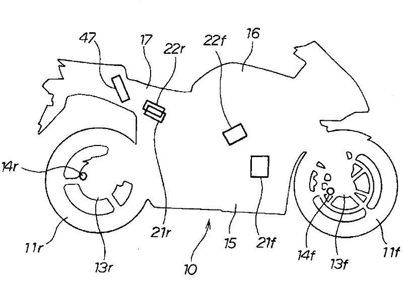
[0048] like figure 1 As shown, the two-wheeled motor vehicle 10 is provided with a pulse generating ring 13f at the front wheel 11f (f is a suffix representing "front". The same applies hereinafter), and a front wheel speed sensor 14f is arranged on the vehicle body 15, so that the front wheel speed can always be detected. The front wheel speed sensor 14f detects the rotational speed of the front wheel 11f by counting the pulses of the pulse generating ring 13f.

[0049] In addition, the motorcycle 10 is equipped with a brake disc 12r and a pulse generating ring 13r on the rear wheel 11r (r is a suffix indicating "rear". The same applies hereinafter), and a rear wheel speed senso...


PUM


Abstract

To provide a brake system capable of realizing a front-rear distribution of braking force according to variations in the running environments. A first control mode and a second control mode are provided by which it is possible to cope with variations in the running environments such as changes between traveling on a public road and traveling on a circuit racecourse and variations in road conditions such as changes between a dry road surface and a wet road surface. A mode change-over switch (26) is disposed between a kill switch (28) on the upper side and a starter switch (29) on the lower side, on the vehicle body center side relative to a right grip (27). Switching between the first control mode and the second control mode is carried out by use of the mode change-over switch (26). By arbitrarily switching over from the first control mode to the second control mode and vice versa, it is possible to perform braking control for a motorcycle corresponding to variations in the running environments.

Description

technical field [0001] The invention relates to a braking device of a two-wheeled motor vehicle. Background technique [0002] A brake device by wire (BBW: Brake By Wire (brake by wire)) has been put into practical use. The brake device (BBW) detects a brake operation amount, generates a hydraulic pressure from a hydraulic regulator based on the detected value, and generates a braking force from the hydraulic pressure. [0003] An ABS (Antilock Brake System (Antilock Brake System)) function can be exhibited by means of the brake device (BBW). [0004] In addition, such a system is known (for example, refer to Patent Document 1 ( figure 1 , image 3 )), by means of the above-mentioned brake device (BBW), in addition to the ABS function, one of the front and rear brake operating elements is operated to make the front and rear wheel brake devices interlock. [0005] The system that links the front and rear wheel brakes is called CBS (Combined Brake System (Combined Brake Sy...

Claims


Application Information

Patent Timeline
15 Aug 2012
Publication
CN102632960A
IPC
B62L3/08; B62L3/02
CPC
B60T8/261; B60T8/1706
Inventors
竹之内和也; 深谷修一