Monitor stand
a technology for monitors and stands, applied in the field of stands, can solve the problems of people being injured, electric appliances could be quickly raised,
- Summary
- Abstract
- Description
- Claims
- Application Information
AI Technical Summary
Benefits of technology
Problems solved by technology
Method used
Image
Examples
first embodiment
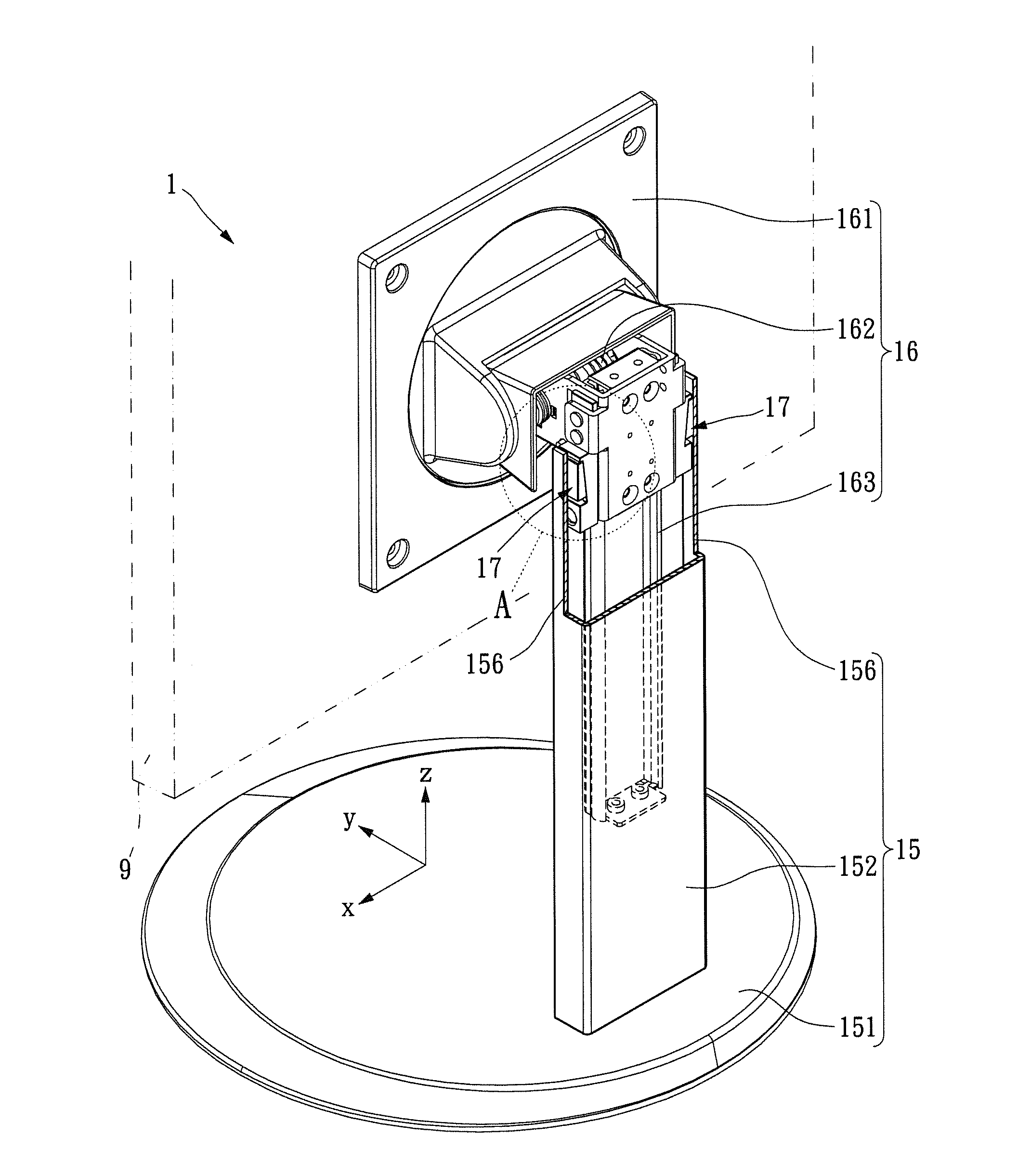
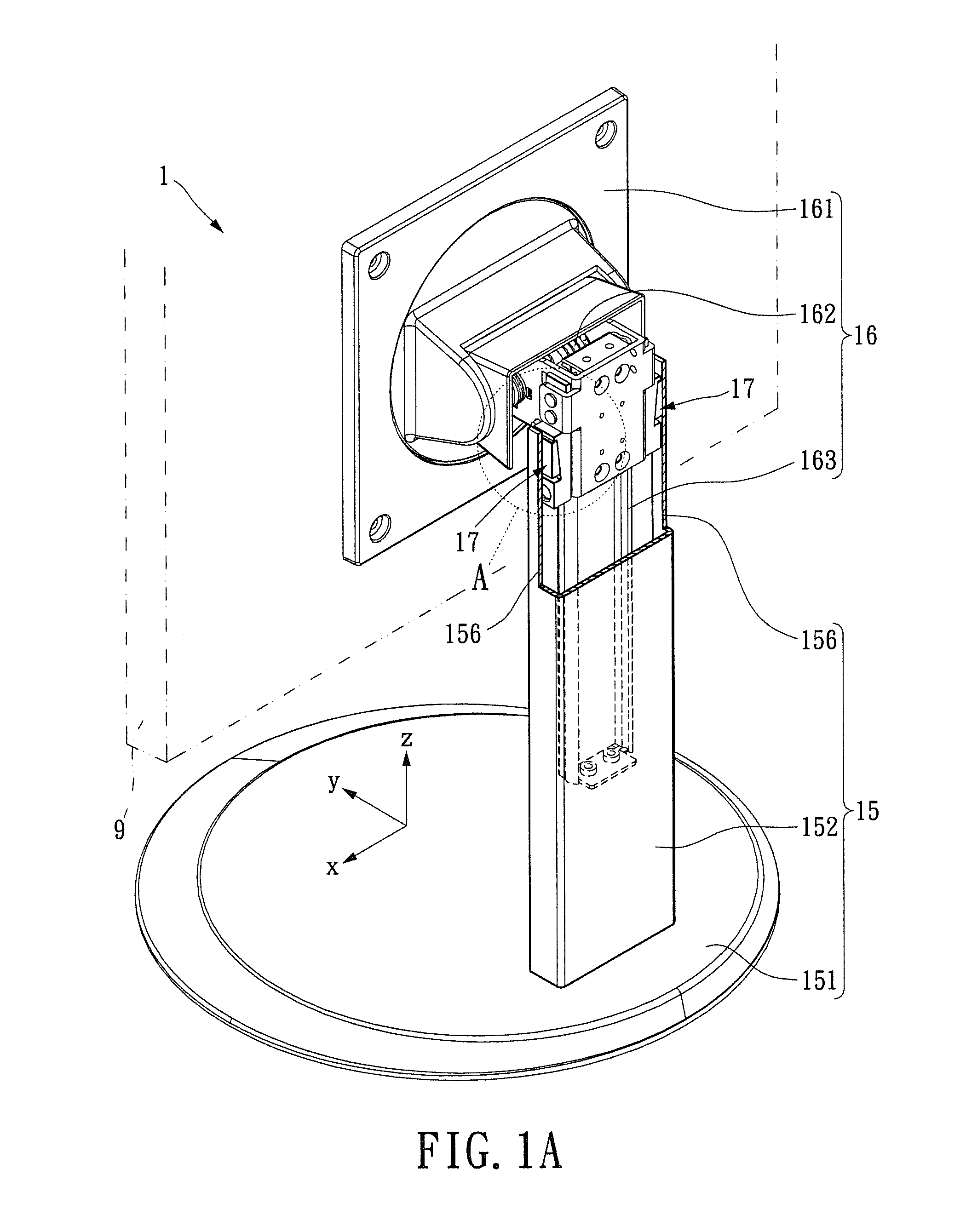
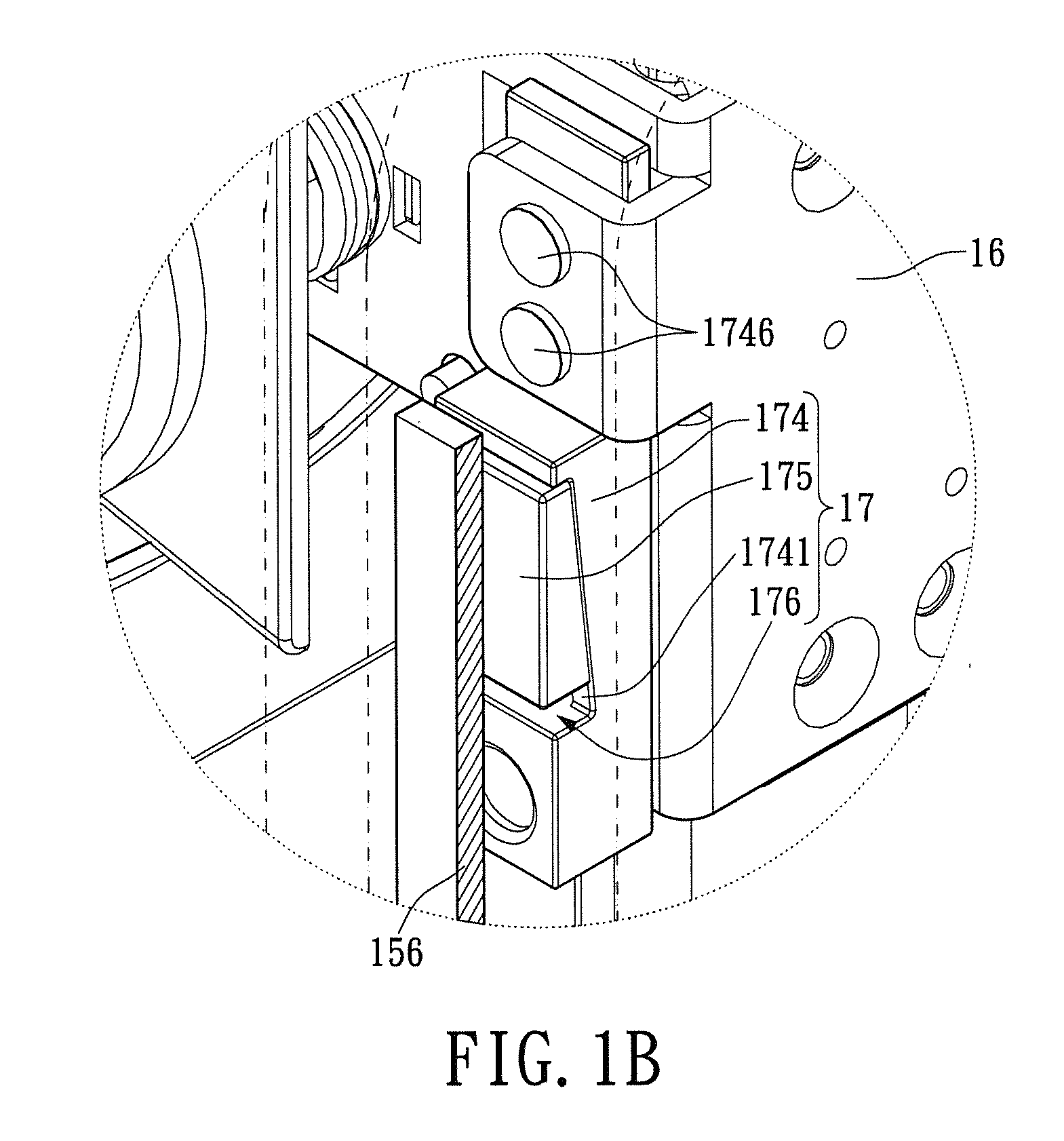
[0033]Please refer to FIGS. 1A and 1B. FIG. 1A is a perspective view of a monitor stand for the present invention. FIG. 1B is an enlarged view of section A in FIG. 1A. As shown in FIGS. 1A and 1B, a monitor stand 1 utilized for supporting a screen unit 9 comprises a supporting unit 15, a mounting unit 16, and a pair of brake units 17. The supporting unit 15 includes a base 151, a pedestal 152, and a pair of contact walls 156. The pedestal 152 has an inner space (unmarked) formed therein and connects to the top surface of the base 151. The contact walls 156 are disposed at inner face of the pedestal 152. The mounting unit 16 includes a holder 161, a rotatable shaft 162, and a guide rail 163. The holder 161 is for connecting to the screen unit 9 and connected to the shaft 162. In this manner, the holder 161 and the screen unit 9 can be rotated. The shaft 162 is slidably connected to the guide rail 163, thus enabling the shaft 162 to move longitudinally along the pedestal 152. In other...
second embodiment
[0051]Please refer to FIGS. 5A and 5B for the present invention. FIG. 5A is sectional view of the monitor stand when the mounting unit is moving upward. Whereas FIG. 5B is sectional view of the monitor stand when the mounting unit is moving downward. For this embodiment, a monitor stand 2 is utilized for supporting a screen unit 9. The monitor stand 2 comprises a supporting unit 25, a mounting unit 26, a pair of contact walls 256, and a pair of brake units (not labeled). Technical features that are similar to the previous embodiment are not discussed again herein. The two brake units of the instant embodiment include two brackets 274, two stoppers 28, and two resisting blocks 275. The brackets 274 are pivotally disposed on the respective side portions of the mounting unit 26, and the resisting blocks 275 are disposed on the surfaces of respective brackets 274 adjacent to the contact wall 256. The stoppers 28 are disposed on opposite side portions of the mounting unit 26 and above th...
fourth embodiment
[0057]Please refer to FIGS. 7A and 7B, which show the monitor stand 4 for the present invention. The monitor stand 4 is structurally similar to the monitor stand 2 of FIGS. 5A and 5B. The main difference is that the brackets 474 are pivotally arranged on the mounting unit 46, with each of the pivoting locations being above the main body of the corresponding bracket 474, while the stoppers 48 are arranged below the pivoting positions of the brackets 474. When the screen unit 9 is being moved downward, the resisting blocks 475 would naturally contact the contact walls 456 parallely (second position). Therefore, the force that needs to be overcame is the upper frictional threshold force. When the screen unit 9 is being moved upward, the brackets 474 and the resisting blocks 475 would rotate downward. Eventually, the brackets 474 are stopped from rotating by the stoppers 48. The resisting blocks 475 contacts the contact walls 456 obliquely (first position). As shown in FIG. 7B, the forc...
PUM
 Abstract
Description
Claims
Application Information
 - R&D
- Intellectual Property
- Life Sciences
- Materials
- Tech Scout
- Unparalleled Data Quality
- Higher Quality Content
- 60% Fewer Hallucinations
Browse by: Latest US Patents, China's latest patents, Technical Efficacy Thesaurus, Application Domain, Technology Topic, Popular Technical Reports.
© 2025 PatSnap. All rights reserved.Legal|Privacy policy|Modern Slavery Act Transparency Statement|Sitemap|About US| Contact US: help@patsnap.com


