Liquid crystal panel and liquid crystal display device

a liquid crystal display and liquid crystal technology, applied in non-linear optics, instruments, optics, etc., can solve the problems of display failure, alignment failure, damage to the alignment film on the electrode, etc., to maintain the durability against external pressure, low wettability of the contact portion, and high reliability of repeated use

Active Publication Date: 2010-06-10
JAPAN DISPLAY WEST
View PDF6 Cites 32 Cited by
  • Summary
  • Abstract
  • Description
  • Claims
  • Application Information

AI Technical Summary

Benefits of technology

[0016]In the liquid crystal panel and the liquid crystal display device according to the embodiments of the present invention, a plurality of pairs of pillar structures may be configured, each pair of pillar structures being arranged on opposing faces of the pair of substrates, respectively, to face each other along a normal to the opposing faces. Thereby, for example, top faces of the pair of pillar structures are directly or indirectly in contact with each other when one or both of the substrates is flexed to a liquid crystal layer side due to external pressure applied thereon. Thereby, with the pillar structures, it is possible to maintain the durability against the external pressure, in the liquid crystal panel. Moreover, in the sensor-mounted device, for example, the tops of the pillar structures are directly or indirectly in contact with each other. Thereby, it is possible to perform the position detection. Here, the portions (hereafter, simply refer to contact portions) in contact with each other with the external pressure are arranged in the positions higher than the other portions, by the height of the pillar structures, respectively. Thus, when forming the alignment films, even when the alignment films are applied over the whole surface, the wettability of the contact portions is low. Therefore, the alignment films are hardly formed, or are not formed at all in the contact portions, respectively. As a result, there is almost no damage, or there is no damage at all on the alignment films due to the external pressure. Thus, reliability of the repeated use is high. Moreover, as described above, since the alignment films are hardly formed, or not formed at all in the contact portions, it is unnecessary to purposely remove a part of the alignment films. Thereby, it is possible to eliminate generation of failure due to the process of removing the alignment films.
[0017]According to the liquid crystal panel and the liquid crystal display device of the embodiments of the present invention, a plurality of pairs of pillar structures may be configured, each pair of pillar structures being arranged on opposing faces of the pair of substrates, respectively, to face each other along a normal to the opposing faces. Thereby, the reliability of the repeated use is high, and it is possible to eliminate generation of the failure due to the process of removing the alignment films. Therefore, it is possible to suppress reduction in the reliability against the external pressure without reducing the yield rate.

Problems solved by technology

However, there is a serious issue in the technique of Japanese Unexamined Patent Publication No. 2007-95044.
Moreover, when the contact with the finger, the pen, or the like is repeated, the alignment film on the electrode is damaged, and may be peeled off.
As a result, there are risks that alignment failure occurs, and the peeled-off alignment film floats in the liquid crystal so that display failure occurs.
Reliability of the repeated use is low.
However, in the case where such a method is used, reduction in the yield rate is caused by various issues such as bleeding of the solvent, an issue of position accuracy, an increase in manufacture cost, reduction in throughput, and splash of the solvent.
Moreover, a device like an inkjet is not used during the typical manufacture process of the liquid crystal.
Thus, existing equipment may not be diverted, and new equipment investment is necessary.
However, since the number of steps increases, reduction in productivity, and the increase in manufacture cost are brought.

Method used


Image

  • Liquid crystal panel and liquid crystal display device
  • Liquid crystal panel and liquid crystal display device
  • Liquid crystal panel and liquid crystal display device

Examples


first embodiment (

1. First embodiment (sensor-mounted type)

2. Modification (spacer)

second embodiment (

3. Second embodiment (pressure-resistant type)

4. Modification (spacer)

first embodiment

Configuration of Liquid Crystal Display Device 1

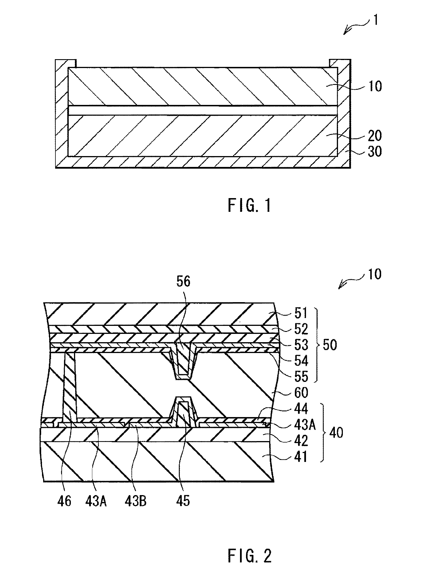
[0039]FIG. 1 illustrates an example of the schematic configuration of a liquid crystal display device 1 according to a first embodiment of the present invention. The liquid crystal display device 1 according to the first embodiment includes a liquid crystal panel 10, a backlight 20 (surface-emitting light source) arranged on a back side of the liquid crystal panel 10, a case 30 supporting the liquid crystal panel 10 and the backlight 20, and a drive circuit (not illustrated in the figure) displaying an image by driving the liquid crystal panel 10. In the liquid crystal display device 1, a front face of the liquid crystal panel 10 (surface on an side opposite from the backlight 20) is oriented to an observer (not illustrated in the figure) side.

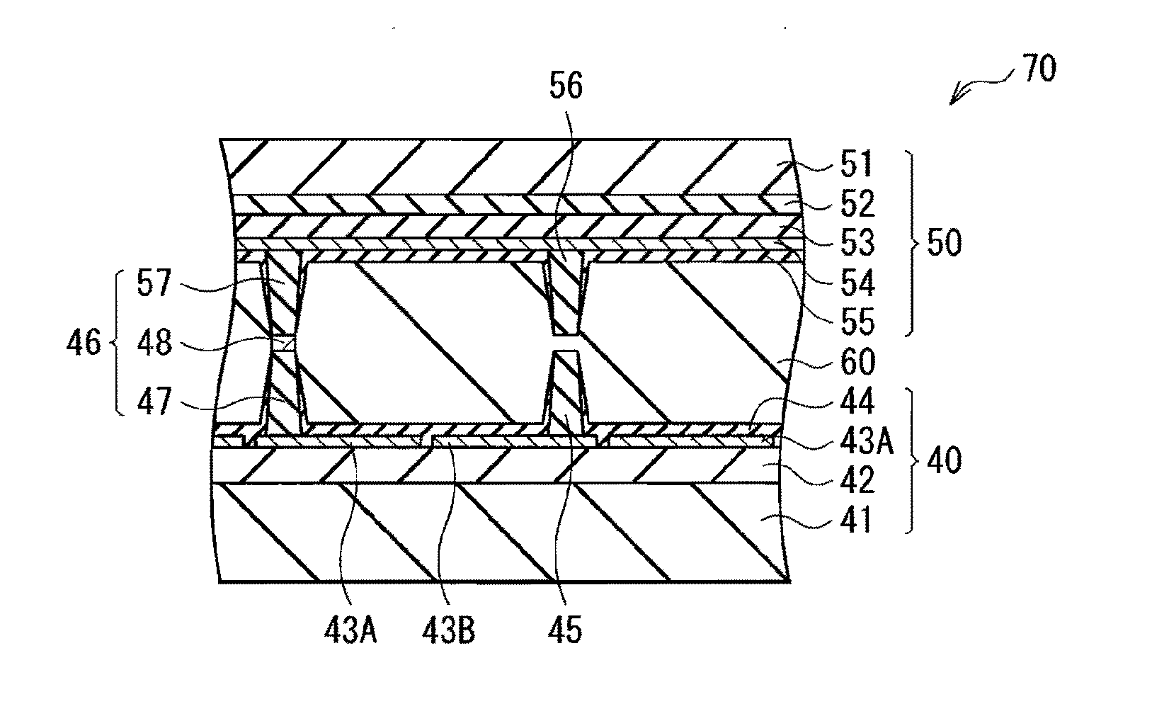
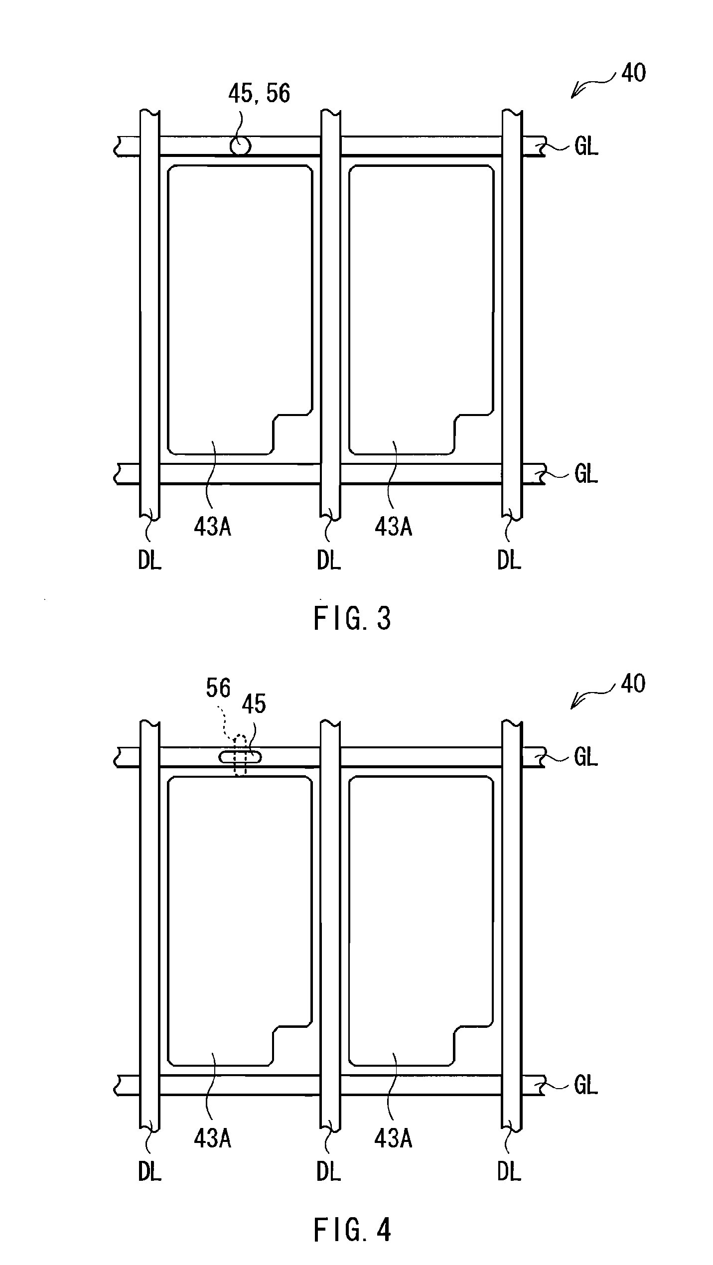
[0040]Liquid Crystal Panel 10

[0041]The liquid crystal panel 10 displays an image. The liquid crystal panel 10 is a so-called sensor-mounted panel, and mounts a sensor function which inputs data w...


PUM

PropertyMeasurementUnit
thicknessaaaaaaaaaa
thicknessaaaaaaaaaa
heightaaaaaaaaaa

Abstract

The present invention provides a liquid crystal panel and a liquid crystal display device allowing reliability deterioration due to external pressure to be suppressed without yield rate degradation. The liquid crystal panel includes: a pair of substrates facing each other with a space in between; a liquid crystal layer disposed in the space between the pair of substrates; and a plurality of pairs of pillar structures, each pair of pillar structures being arranged on opposing faces of the pair of substrates, respectively, to face each other along a normal to the opposing faces.

Description

BACKGROUND OF THE INVENTION[0001]1. Field of the Invention[0002]The present invention relates to a liquid crystal panel in which countermeasures against external pressure are taken, and a liquid crystal display device.[0003]2. Description of the Related Art[0004]A liquid crystal display device has advantages in terms of thinness, light weight, and low electric power consumption. Thus, the liquid crystal display device has been widely used in an electric device for mobile applications, such as a cell-phone, and a digital camera. The liquid crystal display device includes a liquid crystal panel in which a liquid crystal layer is sealed between a pair of substrates. In the liquid crystal display device, light emitted from a backlight which is arranged on a back face of the liquid crystal panel is modulated in the liquid crystal panel, and the modulated light is output from a front face of the liquid crystal panel to the outside, thereby an image display is performed.[0005]In recent yea...

Claims


Application Information

Patent Timeline
Patent Type & Authority Applications(United States)
IPC IPC(8): G02F1/1339G02F1/1337
CPCG02F1/13394
Inventor KOITO, TAKEOHAYASHI, SHUJI
Owner JAPAN DISPLAY WEST
Why Eureka
Try Eureka