Boat for vapor deposition and film formation method using the boat for vapor deposition
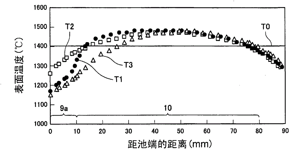
A boat and evaporation technology, which is applied in the field of evaporation boats, can solve the problems of shrinking material evaporation area, lowering the temperature of the heating surface, and the influence of uniform film formation, so as to avoid the sharp drop in temperature and eliminate the effect of droplets
- Summary
- Abstract
- Description
- Claims
- Application Information
AI Technical Summary
Problems solved by technology
Method used
Image
Examples
Embodiment approach 1
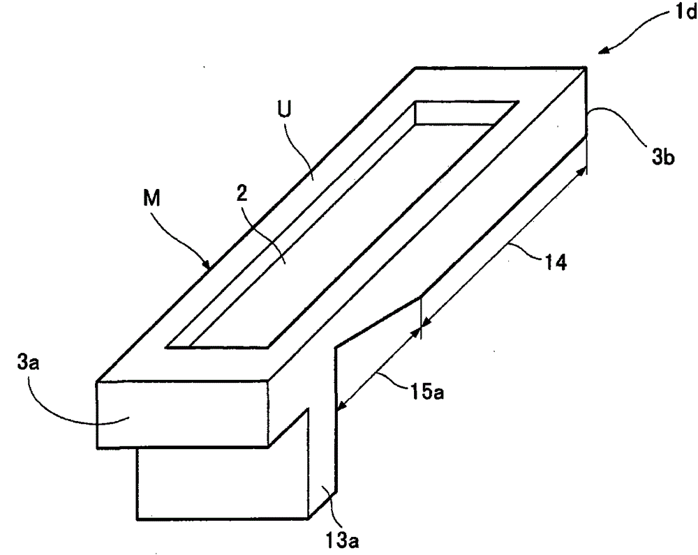
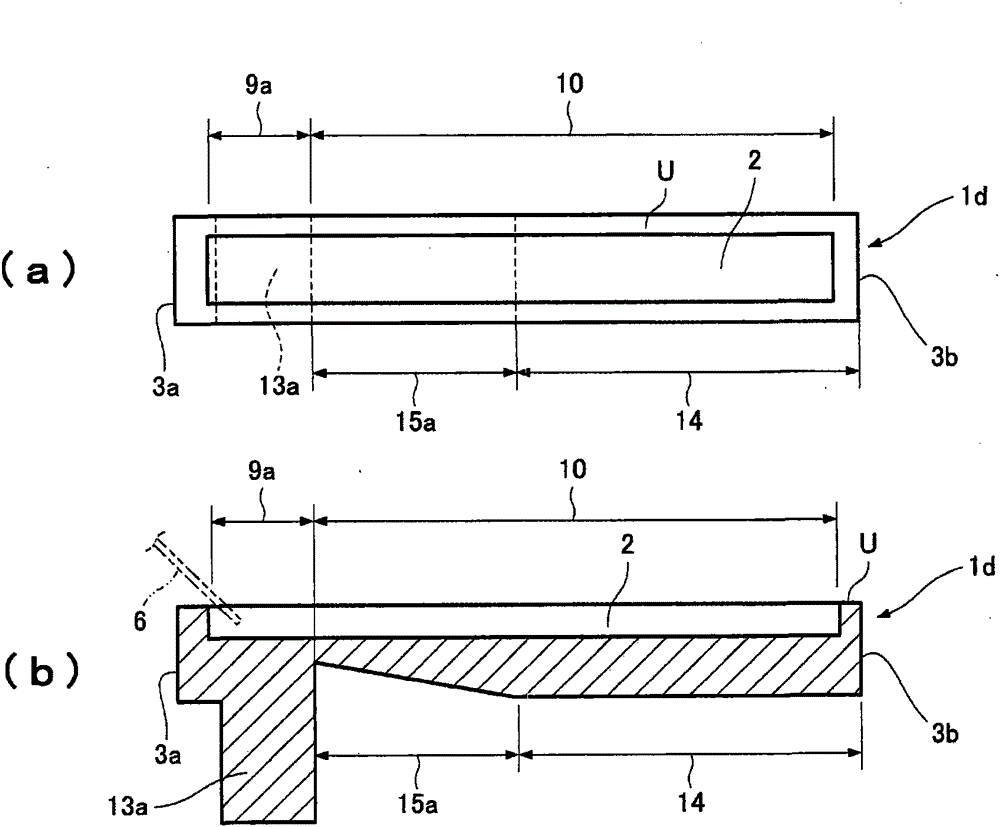
[0064] figure 1 and figure 2 (a), figure 2 (b) shows the boat for vapor deposition of Example 1 of the present invention.
[0065] The vapor deposition boat 1d has a pool 2 for storing molten thin film material formed on the upper surface U extending in the longitudinal direction connecting the one end 3a and the other end 3b of the boat main body M mainly made of graphite. like figure 2 As shown in (b), a protrusion 13a having a cross-sectional area larger than that of the other end 3b is integrally formed near the one end 3a on the back surface of the tank 2 . like figure 2 As shown in (b), a flat portion 14 having a cross-sectional area smaller than that of the protruding portion 13a is formed near the other end 3b on the back surface of the tank 2 . like figure 2 As shown in (b), an inclined portion 15a is formed between the raised portion 13a and the flat portion 14 on the rear surface of the pool 2, and the cross-sectional area of the inclined portion 15a g...
Embodiment approach 2
[0080] Figure 5 and Figure 6 (a), Figure 6 (b), Figure 6 (c) shows the boat for vapor deposition of Example 2 of the present invention.
[0081] In the first embodiment, the protruding portion 13a is formed protrudingly on the back surface of the pool 2, but in the present embodiment 2, the protruding portions 13aa, 13ab are formed protrudingly on the side of the pool 2, which is different from the first embodiment.
[0082] Evaporation boat 1f is made up of pond 2, protruding part 13aa, 13ab, slope part 15aa, 15ab and flat part 14, wherein, above-mentioned protruding part 13aa, 13ab is arranged on the both sides of vapor deposition boat 1f, and above-mentioned slope part 15aa, 15ab are provided adjacent to protrusion parts 13aa, 13ab, and the said flat part 14 is provided adjacent to inclined part 15aa, 15ab.
[0083] In order to maintain the evaporation area, it is desirable that the ratio of the cross-sectional area of the protrusions 13aa, 13ab to the minimum cro...
Embodiment approach 3
[0086] Figure 7 and Figure 8 (a), Figure 8 (b) shows the boat for vapor deposition of Example 3 of the present invention.
[0087] exist figure 1 and figure 2 (a), figure 2 In Example 1 shown in (b), the material supply portion 9a is formed only on the above-mentioned one end 3a side of the pool 2, but in the vapor deposition boat 1g of the present Example 3, the above-mentioned other side of the pool 2 is also formed. A material supply part 9b is formed on the one end 3b side.
[0088] That is to say, a material supply part 9b as a second material supply part connected to the material evaporation part 10 near the other end 3b is provided in the pool 2 to sandwich the material evaporation part 10, and on the back side of the pool 2 near the other end In the vicinity of 3b, a protrusion 13b as a second protrusion having a cross-sectional area larger than that of the flat portion 14 is integrally formed, and a temperature distribution is formed in the pool 2 along th...
PUM
 Abstract
Description
Claims
Application Information
 - R&D
- Intellectual Property
- Life Sciences
- Materials
- Tech Scout
- Unparalleled Data Quality
- Higher Quality Content
- 60% Fewer Hallucinations
Browse by: Latest US Patents, China's latest patents, Technical Efficacy Thesaurus, Application Domain, Technology Topic, Popular Technical Reports.
© 2025 PatSnap. All rights reserved.Legal|Privacy policy|Modern Slavery Act Transparency Statement|Sitemap|About US| Contact US: help@patsnap.com


