
Eject nozzle and eject system

A technology of injection nozzles and gas supply channels, applied in injection devices, liquid injection devices, casting and molding equipment, etc., can solve the problems of large-scale injection units, lag in injection control, and quality reduction, and achieve miniaturization, resistance reduction, The effect of reducing manufacturing cost and construction cost

Inactive Publication Date: 2011-06-08
YUTAKA ELECTRONICS IND
View PDF1 Cites 0 Cited by
  • Summary
  • Abstract
  • Description
  • Claims
  • Application Information

AI Technical Summary

Problems solved by technology

[0005] In the above injection system, since the distance (piping) between the electromagnetic selector valve that controls the air supply and the ejection position of the nozzle is long, the injection control lag occurs, and time is lost in the entire manufacturing cycle. , After spraying, droplets may fall from the tip of the nozzle, causing unnecessary liquid to adhere to the mold, etc., resulting in a decrease in quality
[0006] In addition, since the supply passage for supplying fluid and air to the main body is connected to the main body in a direction perpendicular to the main body, each nozzle is enlarged, resulting in an increase in size and complexity of the ejection unit.

Method used


Image

  • Eject nozzle and eject system
  • Eject nozzle and eject system
  • Eject nozzle and eject system

Examples


Embodiment Construction

[0049] Embodiments of the present invention will be described below with reference to the drawings.

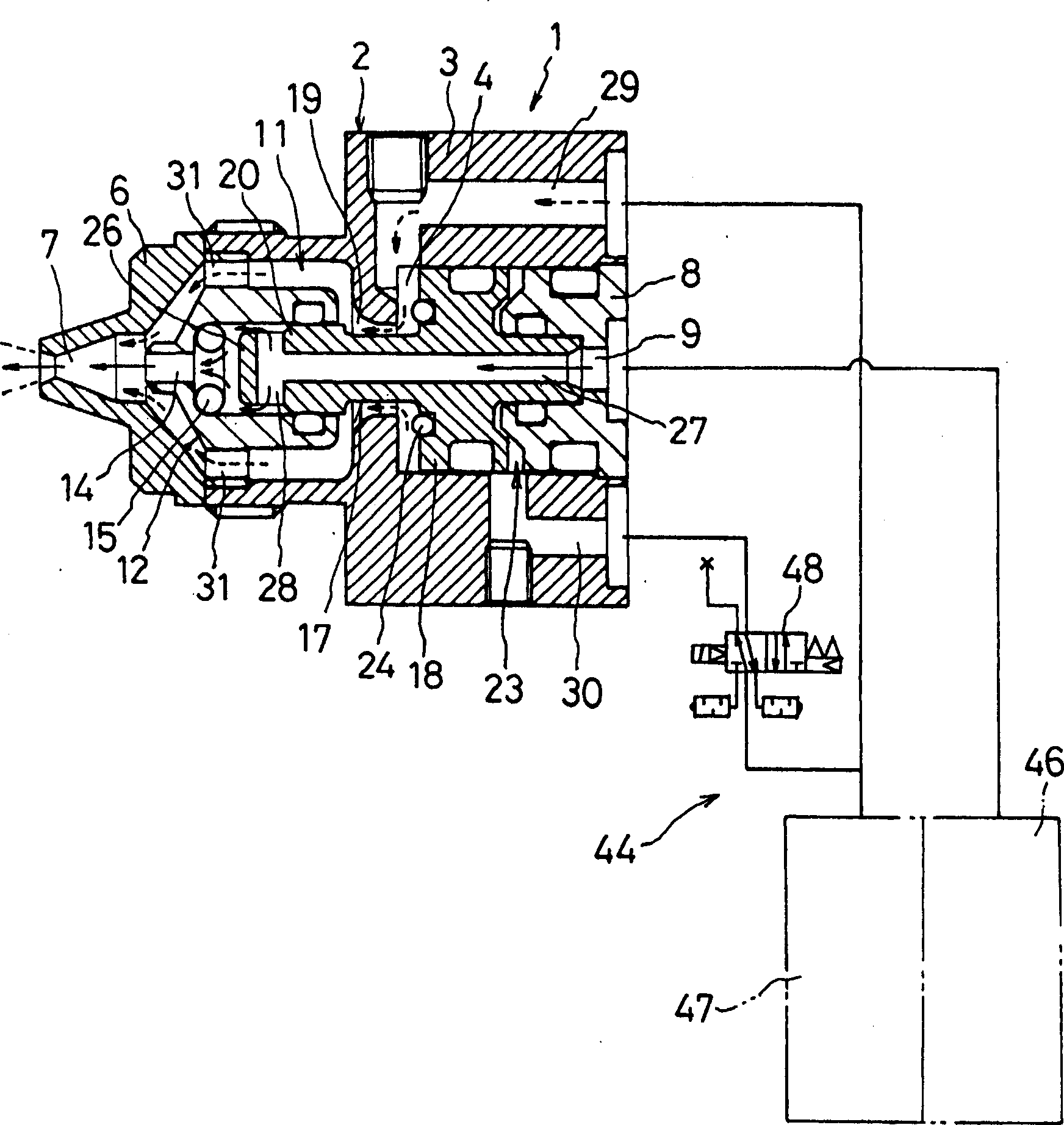
[0050] figure 1 is expressed in image 3 The longitudinal section view of the injection nozzle 1 used instead of the injection nozzle 43 in the shown injection system 40. Here, the manipulator 41 and the injection unit 42 etc. are omitted, and only the injection nozzle 1 and the control panel 44 and the connection between the two are shown. Fluid channels and gas flow channels. The body 2 of the spray nozzle 1 is formed by a body 3 of two-stage diameter, which is at the rear ( figure 1 A piston chamber 4 with a circular cross-section is formed on the axis, and a small-diameter cylindrical portion 5 protrudes from the front; and a cap ring (cap ring) 6 is coaxially connected with the cylindrical portion 5 of the main body 3 , the front end has a spray hole 7 with a thin head. The rear of the piston chamber 4 has a through hole 9 along the axis, which is closed by a piston ...


PUM


Abstract

The present invention provides a spray nozzle and a spray system using the spray nozzle capable of stabilizing process and product quality as well as preventing control delay and liquid dripping. A first piston part and a second piston part are formed on the piston arranged on the axial line of the body in a fore-and-after movable fashion, and a fluid channel ia formed on the axial line. The front side of the plunger compartment is connected with a mixing air channel, and the rear side of the plunger compartment is connected with a control air channel. When the control air channel is suppliedwith compressed air and the piston is forced to advance by the action of the solenoid operated directional valve, the O-shape sealing ring of the first piston part contacts against the inner surface of the plunger compartment to close the air supplying channel, simultaneously the alley part contacts against the O-shape sealing ring to close the fluid supplying channel. On the other hand, when thesolenoid operated directional valve acts to the opposite side, the piston is forced to retract by compressed air from the mixing air channel, and the fluid supplying channel and the air supplying channel are opened, so as to allow a liquid and a gas to mix with each other and execute spray from the spray nozzle.

Description

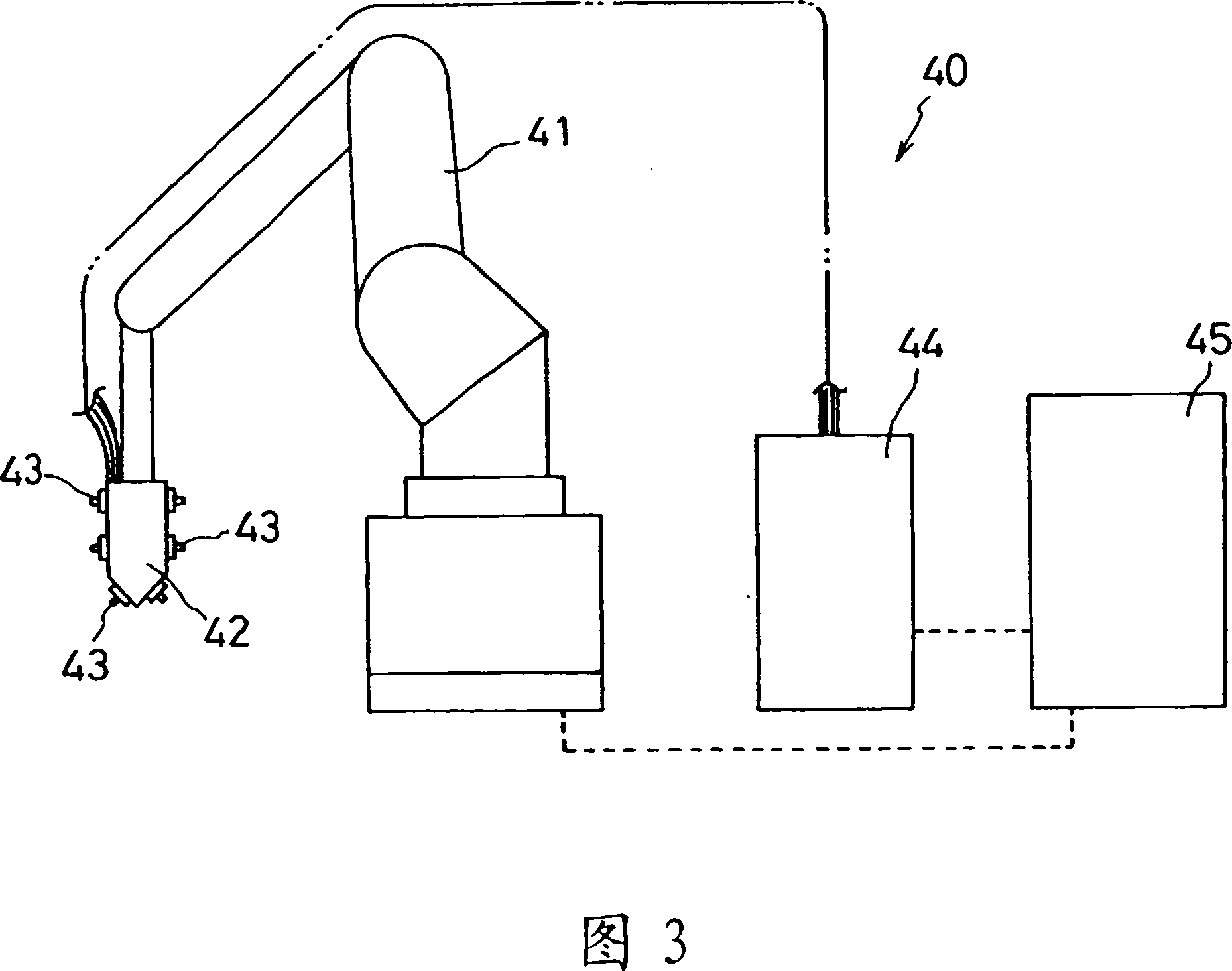
technical field [0001] The present invention relates to a spray nozzle for mixing and spraying fluid and gas, and a spray system using the spray nozzle. For example, spraying mold release agent or cooling water during die casting. Background technique [0002] For example, in the die casting process, in order to release the product from the mold and cool the mold, a spray system that sprays a release agent or cooling water is used. For example, in image 3 In the shown injection system 40, an injection unit 42 is provided at the front end of the manipulator 41 as a mobile control device. On the one hand, a plurality of injection nozzles 43, 43... are arranged side by side on the injection unit 42. Unit 42 is connected with: control panel 44, which has known fluid and gas supply devices made of well-known tanks or pumps, compressors, electromagnetic reversing valves, etc.; The control panel 44 is centrally controlled. [0003] On the other hand, for example, as shown in Pa...

Claims


Application Information

Patent Timeline
Patent Type & Authority Patents(China)
IPC IPC(8): B05B7/02B22D17/20B22C23/02
Inventor 稻垣真一
Owner YUTAKA ELECTRONICS IND
Learn More