Optical navigation module

A technology of optical navigation and optical structure, applied in the direction of instrument, electrical digital data processing, data processing input/output process, etc., can solve the problems of limiting the sensing range and reducing the sensing sensitivity.

Inactive Publication Date: 2012-09-19
SAE MAGNETICS (HK) LTD
View PDF0 Cites 4 Cited by
  • Summary
  • Abstract
  • Description
  • Claims
  • Application Information

AI Technical Summary

Problems solved by technology

At present, some electrical methods have been developed, such as reducing the sensing sensitivity, to limit the sensing range

Method used


Image

  • Optical navigation module
  • Optical navigation module
  • Optical navigation module

Examples


Embodiment Construction

[0018] Reference is made to the preferred embodiments of the optical navigation device of the present application disclosed below. Exemplary embodiments of the optical navigation device disclosed in the present application are described in detail, although certain features that are not essential to understanding the optical navigation device for those skilled in the relevant art have not been described for the sake of clarity.

[0019] In addition, it should be understood that the optical navigation device disclosed in the application of the present invention is not limited to the specific embodiments described below, and those skilled in the art can modify it without departing from the spirit and scope of the present invention. Various changes or equivalent substitutions are made. For example, components and / or features of different exemplary embodiments may be combined with each other and / or substituted for each other within the scope of the present disclosure.

[0020] fi...


PUM


Abstract

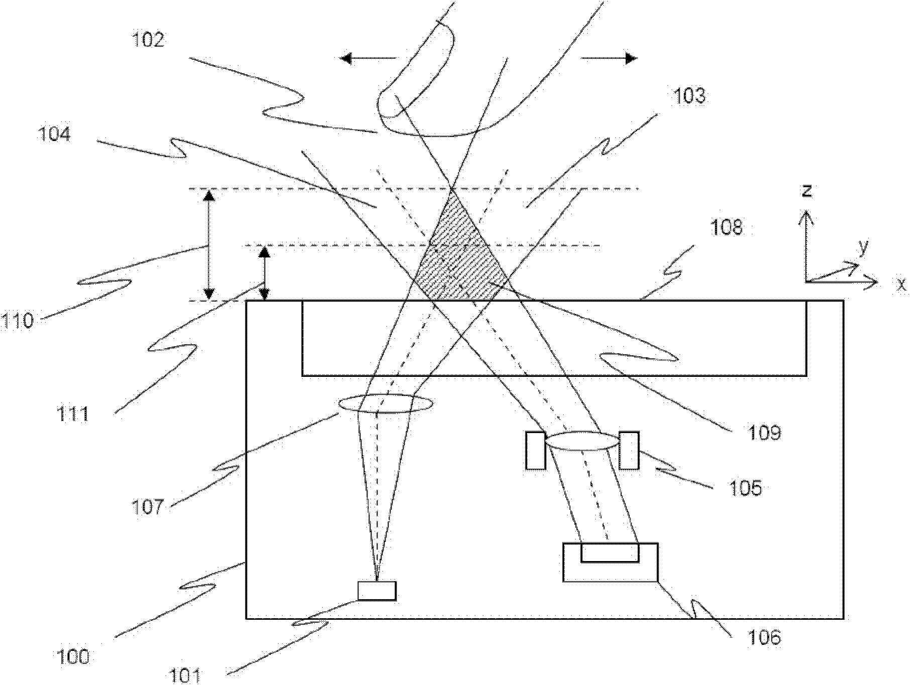
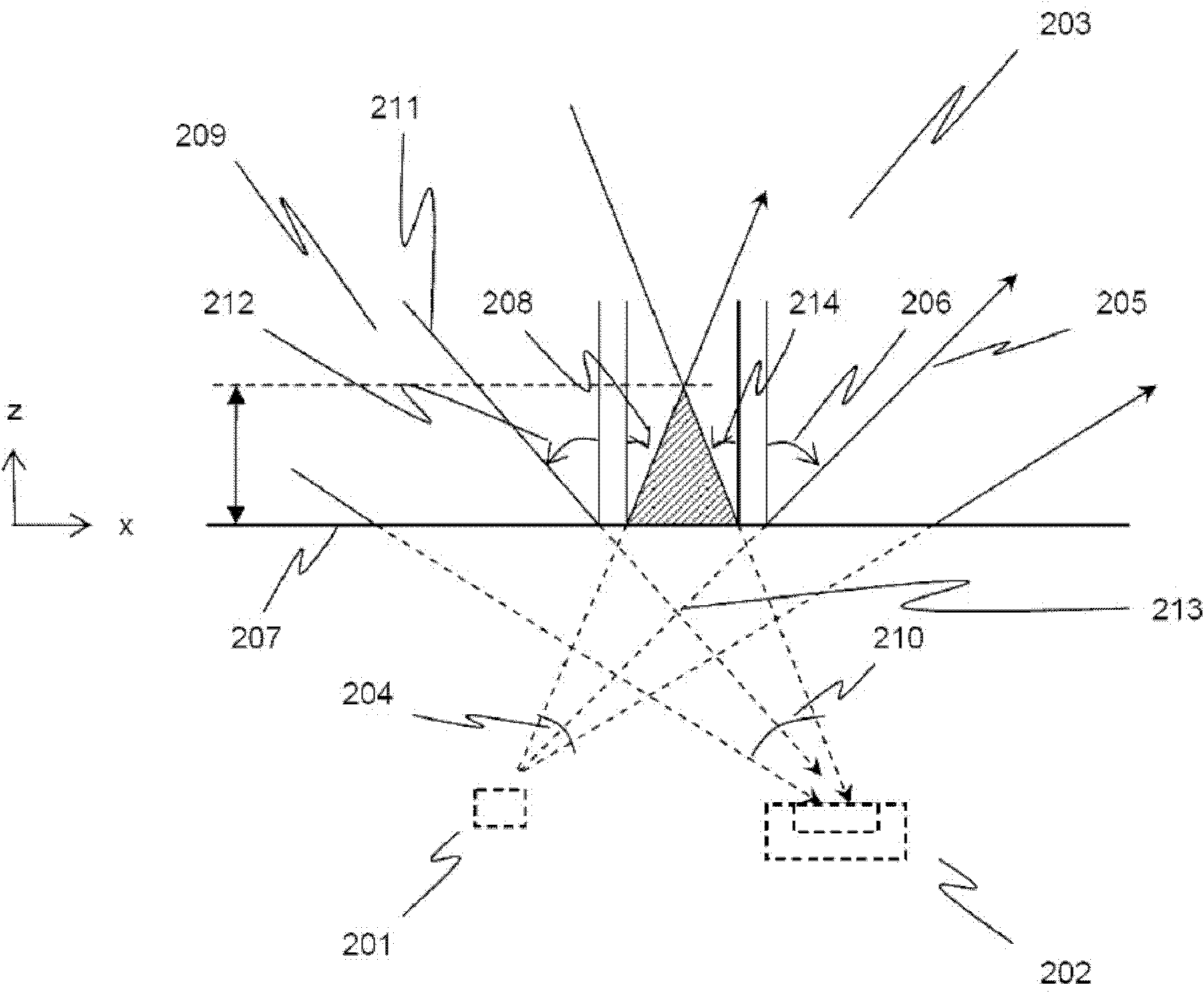
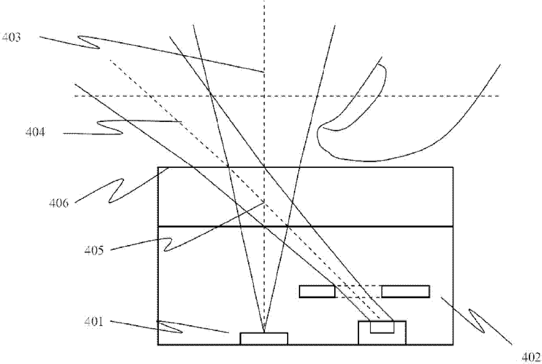
An optical navigation module for receiving control from an object is provided. The optical navigation module includes a module surface above which the object is disposed; a light source located under the module surface and configured to project a first cone of light to the object along a first optical axis through a first optical construction; and a light sensor located under the module surface and configured to detect a second cone of light that is resulted from the first cone of light being reflected by the object along a second optical axis through a second optical construction, and thereby to collect a spatial intensity profile of the reflected light. The intersection of the first optical axis and the second optical axis is below the module surface.

Description

technical field [0001] The present invention relates to optical navigation devices, and more particularly, to a compact and desirable [0002] An optical navigation device with a small sensing range without sacrificing the sensitivity of the light sensor. Background technique [0003] Optical navigation devices are an essential component of consumer electronic products that require user input through a GUI (Graphical User Interface). Existing designs often set the light sensor to receive reflected light as much as possible without considering the sensing range. [0004] In many applications, however, the sensing range of an optical navigation device should be the primary consideration. In these cases, the sensing range must be limited to the available range. Currently, some electrical methods have been developed, such as reducing the sensing sensitivity, to limit the sensing range. Optical navigation devices, on the other hand, are desirably smaller in size, where the se...

Claims


Application Information

Patent Timeline
Patent Type & Authority Applications(China)
IPC IPC(8): G06F3/042
CPCG06F3/0304G06F3/03547G06F3/0421G06F2203/04101
Inventor 吴百康俞晓鸣洪伟
Owner SAE MAGNETICS (HK) LTD
Why Eureka
Try Eureka