Image decoding device, image encoding device, image decoding method, image encoding method, program, and integrated circuit
一种图像解码、图像编码的技术,应用在图像解码装置,图像编码装置领域,能够解决大延迟、效率降低等问题
- Summary
- Abstract
- Description
- Claims
- Application Information
AI Technical Summary
Problems solved by technology
Method used
Image

Examples
Embodiment approach 1
[0136] (1-1. Outline)
[0137] First, the outline of the image decoding device according to Embodiment 1 of the present invention will be described.
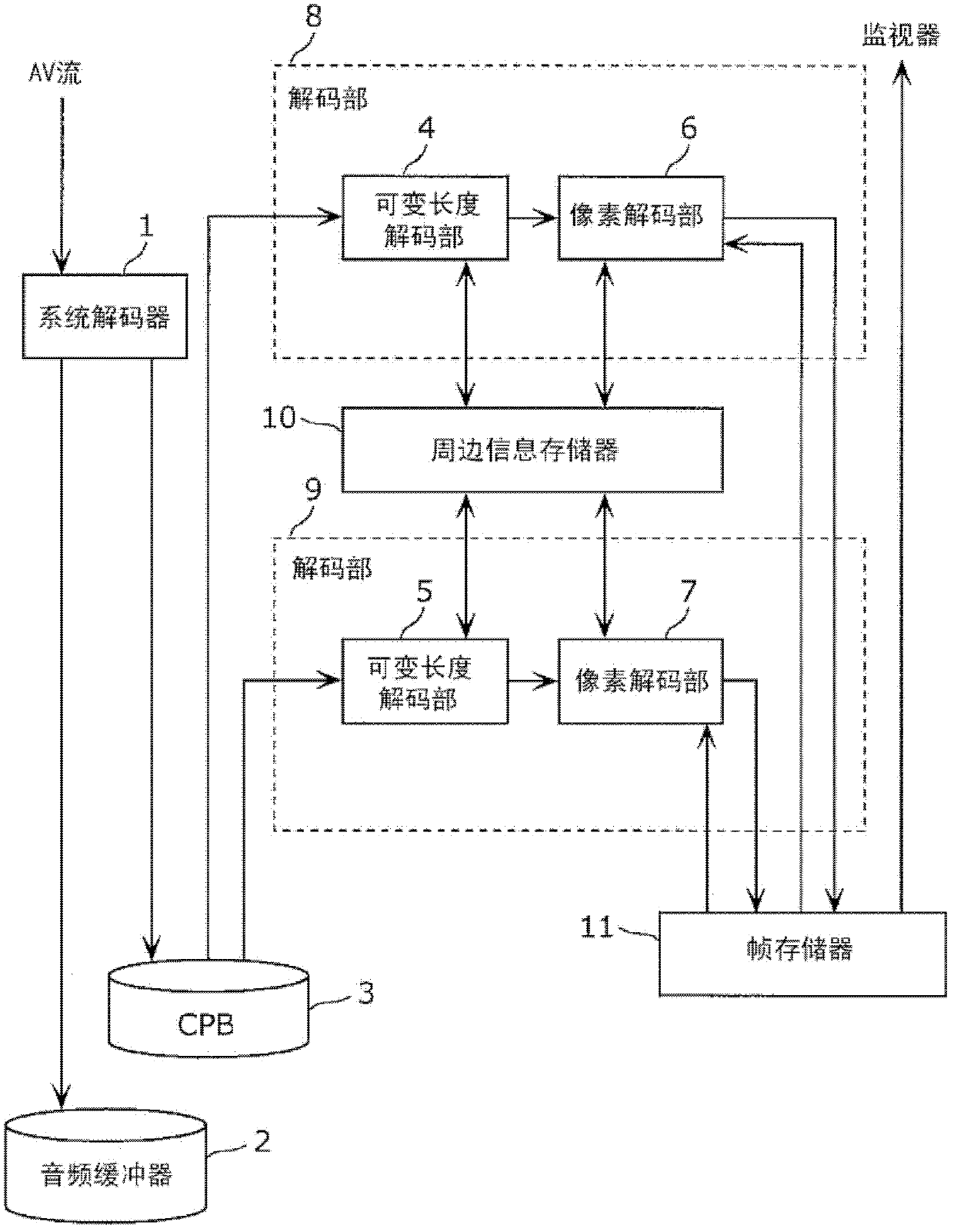
[0138] The image decoding device according to Embodiment 1 of the present invention is configured such that a plurality of decoding units read video streams separated from AV-multiplexed streams by a system decoder. A video stream can be read in advance by a plurality of decoders. The plurality of decoding units perform decoding while being synchronized by referring to a part of the decoding results with each other via the peripheral information memory.
[0139] The above is the description of the outline of the image decoding device according to the present embodiment.
[0140] (1-2. Composition)
[0141] Next, the configuration of the image decoding device according to the present embodiment will be described.
[0142] figure 1 It is a configuration diagram showing the image decoding device of the present embodiment. Th...
Embodiment approach 2
[0253] (2-1. Outline)
[0254] Next, an outline of an image decoding device according to Embodiment 2 of the present invention will be described.
[0255]This embodiment is a method corresponding to CAVLC (Context Adaptive Variable Length Coding, Context Adaptive Variable Length Coding) coding adopted in the H.264 standard as one of the variable length coding methods.
[0256] The above is the description of the outline of the image decoding device according to the present embodiment.
[0257] (2-2. Composition)
[0258] The configuration of the image decoding device of the present embodiment is the same as that of the first embodiment.
[0259] (2-3. Action)
[0260] Next, the description of the operation of the first embodiment is used Figure 8 The operation of this embodiment will be described. Compared with Embodiment 1, the difference in operation is variable length decoding calculation processing (S111).
[0261] Figure 19 It is a figure which shows an example o...
Embodiment approach 3
[0278] (3-1. Outline)
[0279] Next, an outline of an image decoding device according to Embodiment 3 of the present invention will be described.
[0280] In this embodiment, the variable length coding method is arithmetic coding. Since the variable length decoding unit includes an arithmetic decoding unit, the image decoding device according to this embodiment also supports arithmetic decoding.
[0281] The above is the description of the outline of the image decoding device according to the present embodiment.
[0282] (3-2. Composition)
[0283] Next, the configuration of the image decoding device according to the present embodiment will be described.
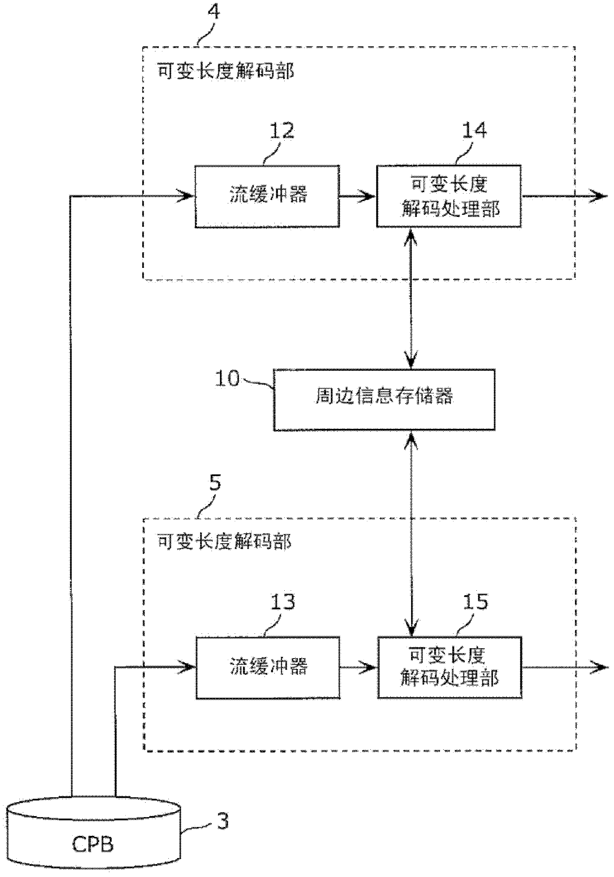
[0284] Figure 20 It is a diagram showing the configuration of the variable-length decoding unit of the image decoding device according to the present embodiment. exist Figure 20 and figure 2 The description of the same constituent elements is omitted. The variable length decoding unit 4 of the present embodiment c...
PUM
 Abstract
Description
Claims
Application Information
 - R&D
- Intellectual Property
- Life Sciences
- Materials
- Tech Scout
- Unparalleled Data Quality
- Higher Quality Content
- 60% Fewer Hallucinations
Browse by: Latest US Patents, China's latest patents, Technical Efficacy Thesaurus, Application Domain, Technology Topic, Popular Technical Reports.
© 2025 PatSnap. All rights reserved.Legal|Privacy policy|Modern Slavery Act Transparency Statement|Sitemap|About US| Contact US: help@patsnap.com