
Novel baby carriage

A new type of baby carriage and frame technology, which is applied in the directions of baby carriage/stroller, multi-axle baby carriage/cradle, baby carriage/cradle accessories, etc., can solve the problems of inconvenient operation, complicated adjustment device and push rod structure, etc. To achieve the effect of convenient operation, simple structure and comfortable use

Inactive Publication Date: 2012-09-26
JIAXING XIAOHUZI BIKE FACTORY CO LTD
View PDF3 Cites 7 Cited by
  • Summary
  • Abstract
  • Description
  • Claims
  • Application Information

AI Technical Summary

Problems solved by technology

[0003] The present invention aims at the problem of complex structure and inconvenient operation of the baby carriage seat adjustment device and the push rod existing in the prior art, and provides an economical, practical and convenient adjustment new baby carriage

Method used


Image

  • Novel baby carriage
  • Novel baby carriage
  • Novel baby carriage

Examples


Embodiment 1

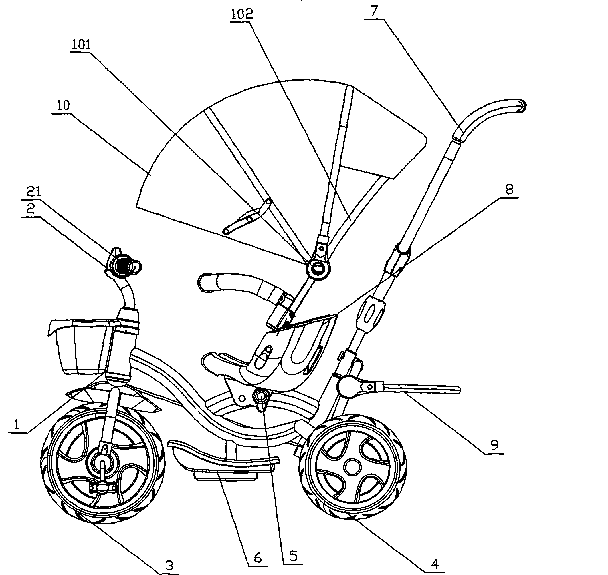
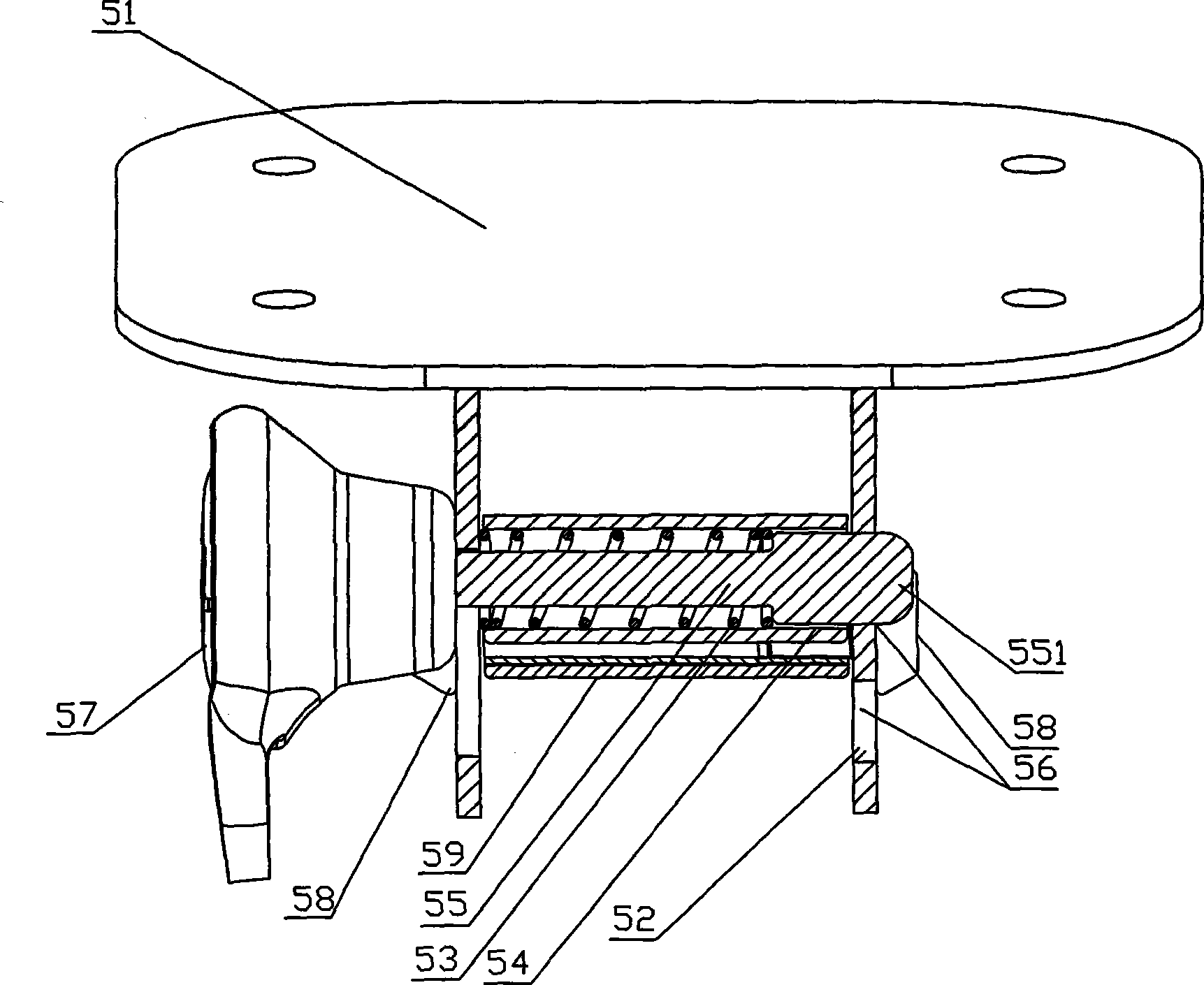
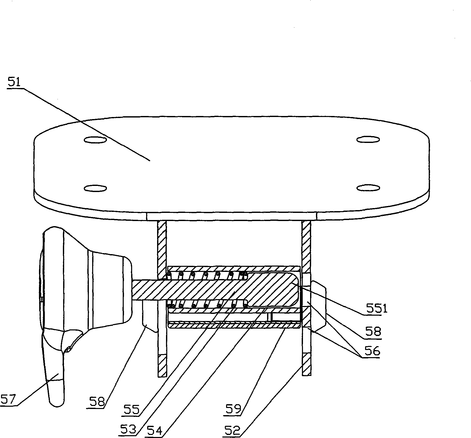
[0026] Such as figure 1 , figure 2 , image 3 , Figure 4 As shown, the novel stroller comprises a vehicle frame 1, a handlebar 2, a seat 8, a front wheel 3, and a rear wheel 4. The vehicle frame 1 below the seat 8 is provided with a pedal 6, and the vehicle frame 1 The rear end is provided with a stroller push rod 7, and the seat 8 is provided with an elevating seat device 5. The elevating seat device 5 includes a seat cushion frame 51 and two support plates 52, and the seat cushion frame 51 is located on the support plate 52. Above, the support plate 52 is provided with a set screw 58, a screw pin 59, a spring 53, a fixed tube 54 and a movable rod 55, and the spring 53 is arranged between the fixed tube 54 and the movable rod 55. The support plate 52 is provided with two holes 56 through which the end 551 of the movable pull rod 55 can pass through, and the outer side of the movable pull rod 55 is connected with a pull handle 57 through a fixing screw 58 . The handlebar...

Embodiment 2

[0028] Such as figure 1 , figure 2 , image 3 , Figure 4 , Figure 5 , Image 6 , Figure 7 and Figure 8As shown, the novel stroller comprises a vehicle frame 1, a handlebar 2, a seat 8, a front wheel 3, and a rear wheel 4. The vehicle frame 1 below the seat 8 is provided with a pedal 6, and the vehicle frame 1 The rear end is provided with a stroller push rod 7, and the seat 8 is provided with an elevating seat device 5. The elevating seat device 5 includes a seat cushion frame 51 and two support plates 52, and the seat cushion frame 51 is located on the support plate 52. Above, the support plate 52 is provided with a set screw 58, a screw pin 59, a spring 53, a fixed tube 54 and a movable rod 55, and the spring 53 is arranged between the fixed tube 54 and the movable rod 55. The support plate 52 is provided with two holes 56 through which the end 551 of the movable pull rod 55 can pass through, and the outer side of the movable pull rod 55 is connected with a pull ...


PUM


Abstract

The invention relates to a seat technology for a baby carriage, and discloses a device capable of lifting a baby carriage seat. A novel baby carriage comprises a frame, a handlebar, a seat, a front wheel and a rear wheel, wherein a pedal is arranged on the frame below the seat; a baby carriage push rod is arranged at the rear end of the frame; a seat lifting device is arranged below the seat and comprises a seat cushion frame and a plurality of support plates; the seat cushion frame is positioned above the support plates; a fixing screw, a screw rod pin, a spring, a center passing fixing pipe and a movable pull rod are arranged among the support plates; the spring is arranged between the center passing fixing pipe and the movable pull rod; a plurality of holes through which the end of the movable pull rod can pass are formed on the support plates; and the outer side of the movable pull rod is connected with a pull handle through the fixing screw. According to the technical scheme, the requirements of children with different heights on different heights of the seat can be met, and the novel baby carriage has the advantages that the baby carriage has a simple structure, is convenient to operate, reliably locked and comfortably used, and the like.

Description

technical field [0001] The invention relates to seat technology on a baby carriage, in particular to a convenient and practical novel baby carriage. Background technique [0002] The height of the seat on the existing baby carriages is generally not adjustable, although some are adjustable, but the structure is complicated, and some cannot adjust the height or inclination of the seat quickly according to the height requirements of the child, and some adjustments take a lot of time. It takes a lot of time and energy. In addition, the push rods on the existing baby carriages are simple in structure and single in function. Few of them can be adjusted in height. Even if they are, they are conventional adjustment methods. Therefore, how to design a baby carriage seat adjustment device and a baby carriage push rod with simple structure, convenient operation, reliable adjustment and comfortable use has become a big problem that needs to be solved urgently in this field. Contents ...

Claims


Application Information

Patent Timeline
Patent Type & Authority Applications(China)
IPC IPC(8): B62B7/04B62B9/20
Inventor 吴春华吴新良干月明
Owner JIAXING XIAOHUZI BIKE FACTORY CO LTD
Learn More