Supercharge Your Innovation With Domain-Expert AI Agents!

Air shaft and transmission shaft component of mechanical lap winder

A technology of transmission shaft and air expansion shaft, which is applied in the structural field of transmission mechanism, and can solve the problems that mechanical coiling cannot be applied.

Inactive Publication Date: 2012-09-26
江苏汉高德瑞实业有限公司
View PDF7 Cites 0 Cited by
  • Summary
  • Abstract
  • Description
  • Claims
  • Application Information

AI Technical Summary

Problems solved by technology

[0002] Usually, the shaft head of the air expansion shaft and the shaft head of the transmission shaft are connected in a square shape. This connection method is only limited to double-roller rolls, and it is not applicable to mechanical rolls.

Method used


Image

  • Air shaft and transmission shaft component of mechanical lap winder
  • Air shaft and transmission shaft component of mechanical lap winder

Examples


Embodiment Construction

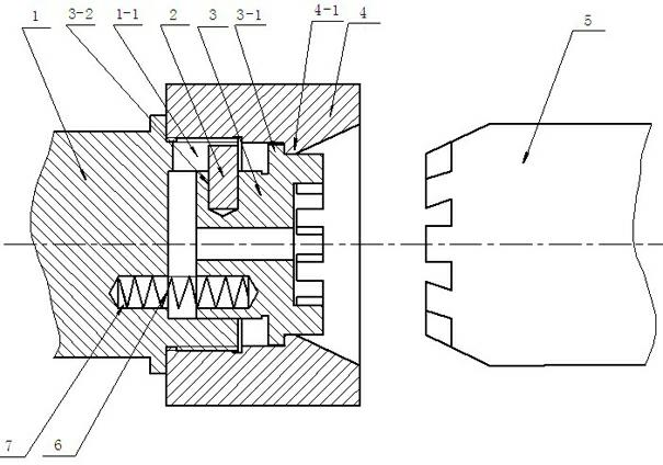
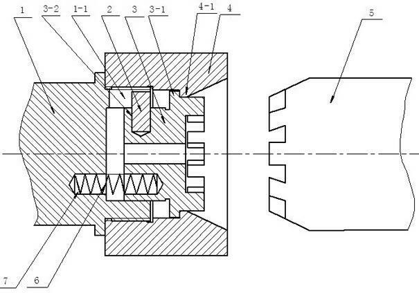
[0009] Such as figure 1 Shown is the pneumatic shaft drive shaft assembly of a mechanical winder, including a coaxially arranged drive shaft 1 and an inflatable shaft 5. The end of the drive shaft 1 facing the inflatable shaft 5 is provided with a drive shaft head 3 and a drive shaft shaft Sleeve 4, the transmission shaft sleeve 4 is threadedly connected with the transmission shaft 1, the transmission shaft head 3 is arranged in the transmission shaft sleeve 4, the transmission shaft sleeve 4 is radially provided with a sleeve limit boss 4-1, the transmission shaft shaft A shaft head limiting boss 3-1 is arranged radially outside the head 3, and the shaft head limiting boss 3-1 is arranged between the transmission shaft 1 and the shaft sleeve limiting boss 4-1. The opposite ends of the transmission shaft 1 and the transmission shaft head 3 are axially provided with three groups of spring holes 7, and each group of spring holes 7 is respectively provided with a spring 6. Three ...


PUM


Abstract

The invention relates to an air shaft and transmission shaft component of a mechanical lap winder, and belongs to the field of transmission structures of the mechanical lap winder. The component comprises an air shaft and a transmission shaft coaxially arranged. A transmission shaft head and a transmission shaft sleeve are arranged on the transmission shaft at the end towards the air shaft, wherein the transmission shaft sleeve is in threaded connection with the transmission shaft, and the transmission shaft head is arranged inside the transmission shaft sleeve; shaft sleeve limit lug boss is formed axially in the transmission shaft sleeve, and a shaft head limit lug boss is formed axially outside the transmission shaft head and arranged between the shaft sleeve limit lug boss and the transmission shaft; spring holes are axially formed on the opposite end faces of the transmission shaft and the transmission shaft head, and springs are arranged in the spring holes; and the opposite faces of the transmission shaft head and the air shaft are tooth faces which can be separated and meshed with each other. The component provided by the invention is applicable to mechanical winding.

Description

Technical field [0001] The invention relates to the structure field of a transmission mechanism of a mechanical coiling machine. Background technique [0002] Generally, the shaft head of the inflatable shaft and the shaft head of the drive shaft are connected in a square shape. This connection method is limited to double-roller rolling, and is not applicable to mechanical rolling. Summary of the invention [0003] The purpose of the present invention is to overcome the shortcomings of the prior art and provide a pneumatic shaft drive shaft assembly of a mechanical winding machine, which is suitable for mechanical winding. [0004] The purpose of the present invention is achieved as follows: The pneumatic shaft drive shaft assembly of a mechanical winder includes a drive shaft and an inflatable shaft arranged coaxially, and an end of the drive shaft facing the inflatable shaft is provided with a drive shaft head and a transmission The shaft sleeve, the transmission shaft sleeve and...

Claims


Application Information

Patent Timeline
IPC IPC(8): B65H79/00
Inventor 徐光耀
Owner 江苏汉高德瑞实业有限公司
Features
  • R&D
  • Intellectual Property
  • Life Sciences
  • Materials
  • Tech Scout
  • Unparalleled Data Quality
  • Higher Quality Content
  • 60% Fewer Hallucinations
Learn More