Shift cylinder, drive device, work machine as well as method for operating a work machine

A driving device and control cylinder technology, which is applied in the direction of transmission, fluid transmission, transmission control, etc., can solve problems such as undesired switching, multi-plate clutch accident, transmission hydraulic motor damage, etc., so as to avoid unwanted Effects of decoupling, light weight, and avoidance of switching

Active Publication Date: 2012-09-26
NAF NEUNKIRCHENER ACHSENFABRIK
View PDF6 Cites 6 Cited by
  • Summary
  • Abstract
  • Description
  • Claims
  • Application Information

AI Technical Summary

Problems solved by technology

Accordingly, in the event of a sudden pressure loss, an unexpected and undesired switching of the multi-disc clutch can result, for example, in the case of a sudden decoupling or mutual coupling of the hydraulic motors
Failure to take appropriate measures can also result in damage to the transmission and / or hydraulic motor

Method used


Image

  • Shift cylinder, drive device, work machine as well as method for operating a work machine
  • Shift cylinder, drive device, work machine as well as method for operating a work machine
  • Shift cylinder, drive device, work machine as well as method for operating a work machine

Examples


Embodiment Construction

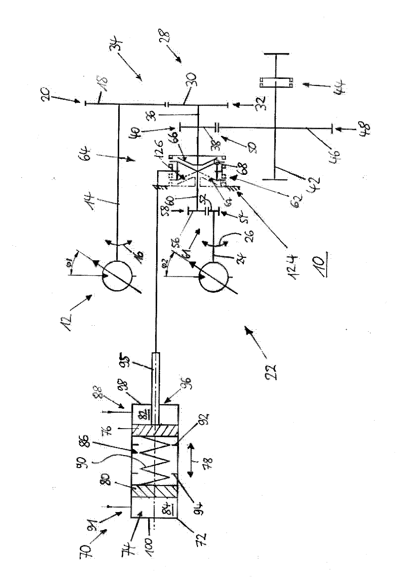
[0057] figure 1 A drive 10 for a self-propelled agricultural machine is shown. The drive device 10 includes a first hydraulic motor 12 which can be driven by hydraulic oil. The hydraulic motor 12 comprises a driven shaft 14 which is rotatable about a rotational axis in a first rotational direction and in a second rotational direction opposite to the first rotational direction. The rotation of the driven shaft is indicated by directional arrow 16 . A gear wheel 18 is connected in a rotationally fixed manner to the output shaft 14 , and has a toothing 20 . The gear 18 is formed as a spur gear, for example.

[0058] The drive device 10 includes a second hydraulic motor 22 which can be driven by hydraulic oil. To drive the first hydraulic motor 12 and the second hydraulic motor 22 , the two hydraulic motors 12 and 22 are supplied with hydraulic oil via only one pump device of the drive device 10 which is common to the hydraulic motors 12 and 22 . The drive device 10 thus has ...


PUM


Abstract

The invention relates to a shift cylinder (70) including a cylinder element (72) having a working space (74), a first and a second piston (76, 80) received in the working space (74) displaceably relatively to it, by which the working space (74) is divided in a first working chamber (82) capable of being charged with a working medium through a first port (88) of the shift cylinder (70), a second working chamber (84) capable of being charged with a working medium through a second port (91) of the shift cylinder (70) and a third working chamber (86) disposed between the first and the second working chamber (82, 84), including at least one spring member (90) capable of being supported on the first piston (76) on the one hand and on the second piston (80) on the other hand, by means of which a force can be bilaterally applied to the pistons (76, 80), wherein a first stop (92); of the shift cylinder (70) is associated with the first piston (76), by means of which a movement of the first piston (76) towards the second piston (80) is confined, and wherein a second stop (94) of the shift cylinder (70) is associated with the second piston (80), by means of which a movement of the second piston (80) towards the first piston (76) is confined.

Description

technical field [0001] The invention relates to a control cylinder, a drive device of the type according to the general concept of claim 10 , an operating machine and a method of operating an operating machine of the type according to the general concept of claim 16 . Background technique [0002] Document DE 44 04 829 A1 discloses a load-controlled transmission for mobile construction machines and operating machines with at least two hydraulic motors drivable via at least one pump, the hydraulic motors being driven by the input One side of the shaft is respectively effectively connected with at least one gear pair. For the first maximum stroke of the construction machine and the operating machine, the hydraulic motors are interconnected via a clutch for summing the torques of the two hydraulic motors. The load-controlled transmission also includes a planetary transmission having at least one output shaft, the ring gear of which can be fixed via at least one brake. In this...

Claims


Application Information

Patent Timeline
Patent Type & Authority Applications(China)
IPC IPC(8): F15B15/08F16D25/12F16H47/00
CPCF16H2047/025F16H2061/307F15B15/1409F16H47/02F16H61/30
Inventor B·施纳贝尔
Owner NAF NEUNKIRCHENER ACHSENFABRIK
Why Eureka
Try Eureka