

Mold base pressing structure of extruding machine
A compression structure and extrusion press technology, applied in metal extrusion forming tools, metal extrusion, metal processing equipment, etc. The effect of simplified component structure, convenient replacement and firm installation
- Summary
- Abstract
- Description
- Claims
- Application Information
AI Technical Summary
Problems solved by technology
Method used
Image

Examples
Embodiment Construction
[0021] Typical embodiments embodying the features and advantages of the present invention will be described in detail in the following description. It should be understood that the invention is capable of various changes in different embodiments without departing from the scope of the invention, and that the description and illustrations therein are illustrative in nature and not limiting. this invention.
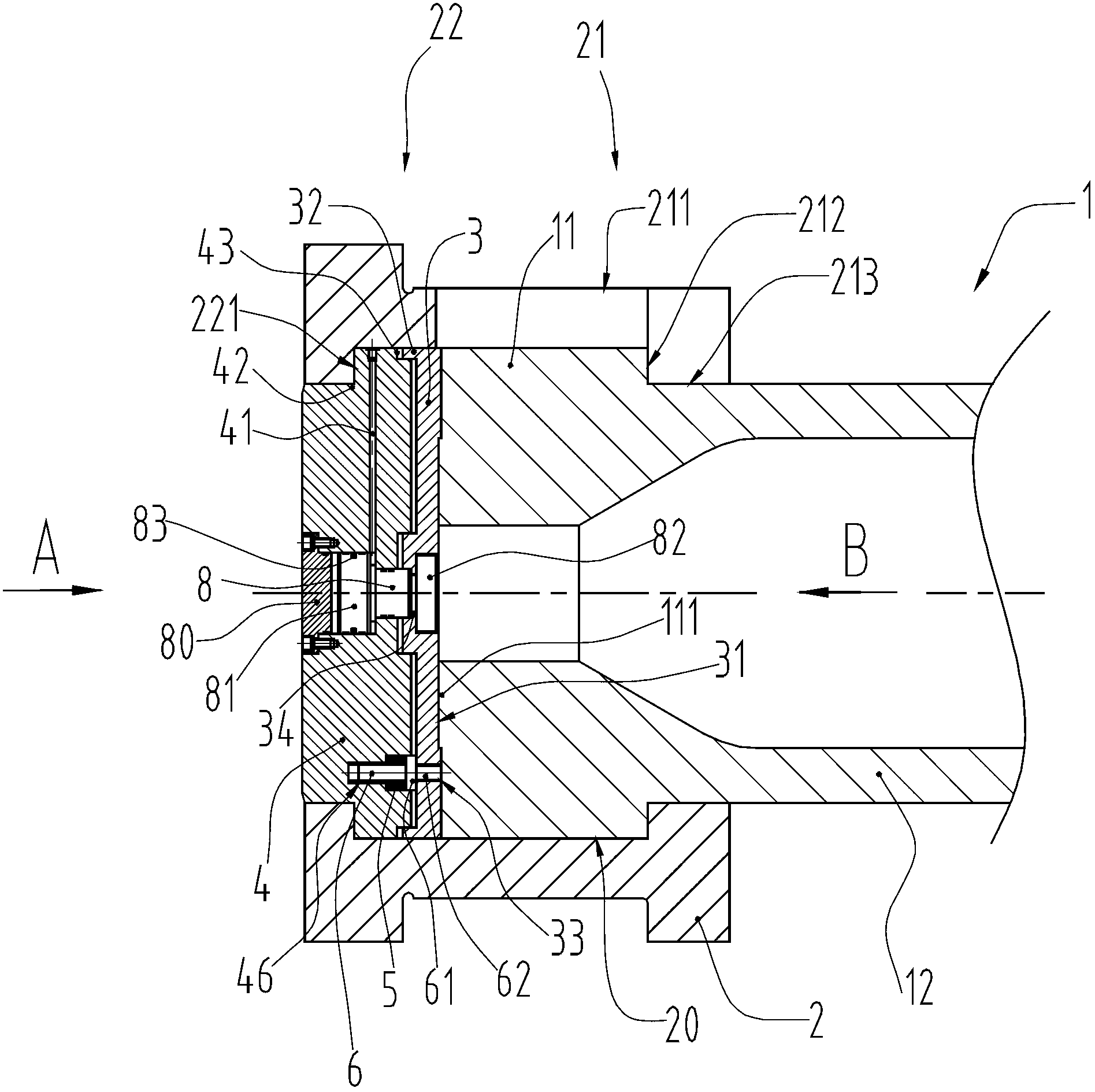
[0022] Such as figure 1 Shown: the present invention provides a die base compression structure of an extruder, including a tool bar 1 and a die base 2 for fixing the tool bar 1, the tool bar 1 mentioned here is the existing reverse metal extrusion machine Tools such as push rod or cleaning sleeve, general main body is cylinder 12, for being able to cooperate mold base 2 to carry out compression, rear end is set as the chuck 11 that radially protrudes from cylinder 12.
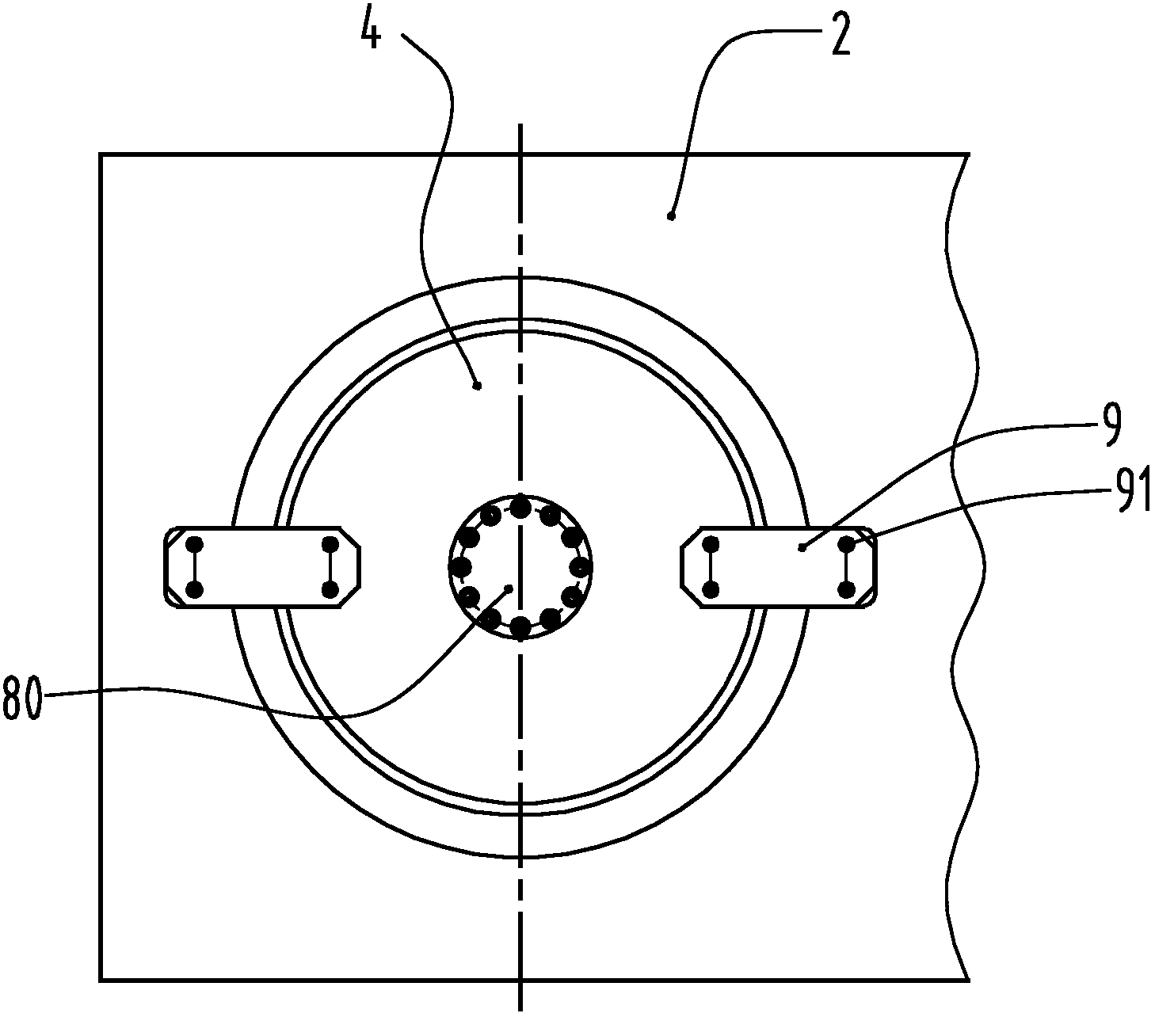
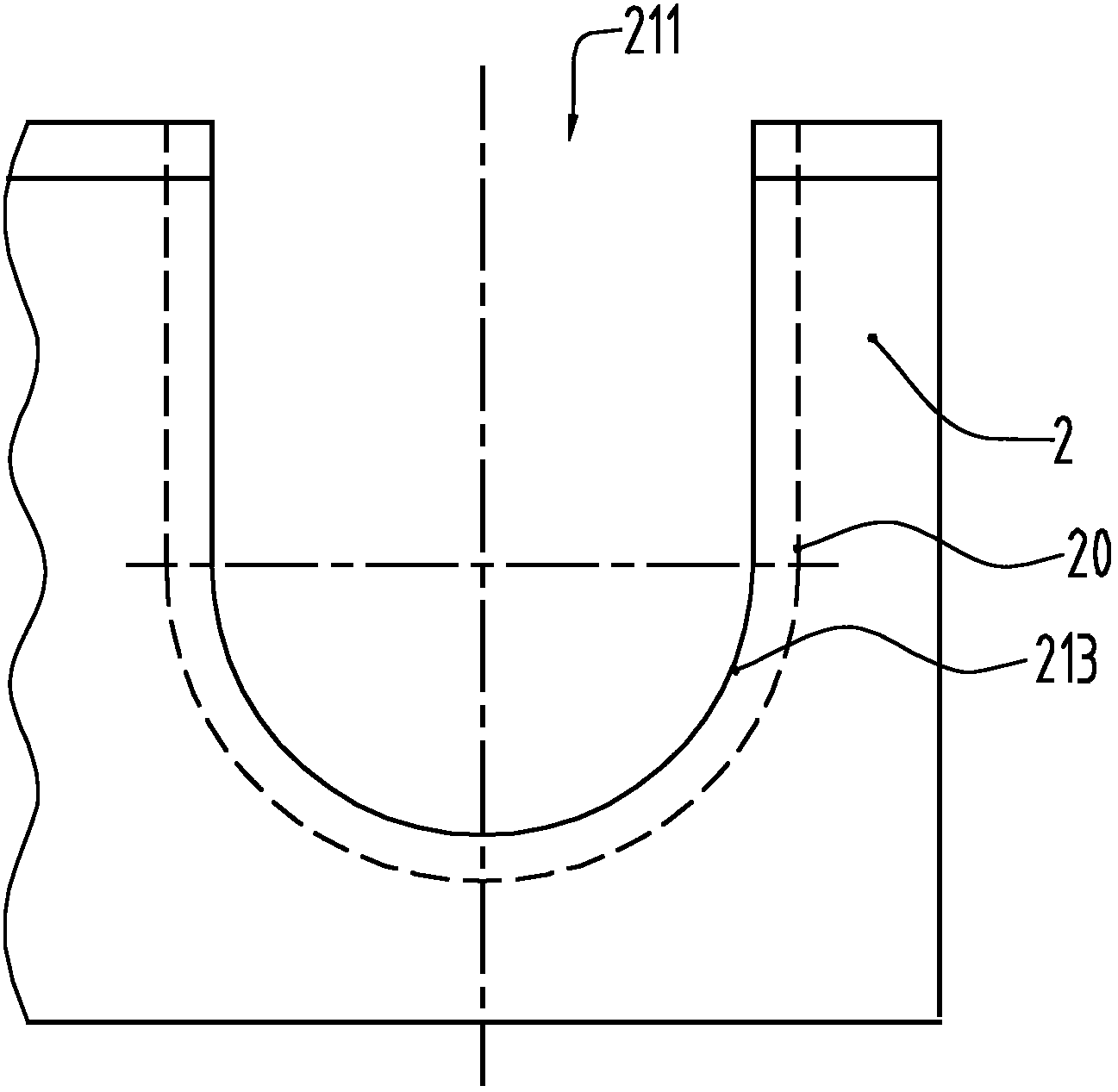
[0023] The main technical idea of the present invention is that, as figure 1 , image 3 , Figure ...
PUM
 Abstract
Description
Claims
Application Information