Control circuit and control method of low-voltage reactive compensation device

A compensation device and control circuit technology, applied in reactive power compensation, reactive power adjustment/elimination/compensation, etc., can solve frequent switching problems, achieve small inrush current, low power consumption, and overcome frequent switching problems

Active Publication Date: 2012-10-03
CHINA ELECTRIC POWER RES INST +1
View PDF2 Cites 10 Cited by
  • Summary
  • Abstract
  • Description
  • Claims
  • Application Information

AI Technical Summary

Problems solved by technology

[0004] Aiming at the deficiencies of the prior art, the present invention provides a low-voltage reactive power compensation device and its control method, which overcomes the shortcomings of the existing low-voltage reactive power compensation device and the frequent switching problems that easily occur in the existing nine-zone map control

Method used


Image

  • Control circuit and control method of low-voltage reactive compensation device
  • Control circuit and control method of low-voltage reactive compensation device
  • Control circuit and control method of low-voltage reactive compensation device

Examples


Embodiment Construction

[0043] The specific implementation manners of the present invention will be further described in detail below in conjunction with the accompanying drawings.

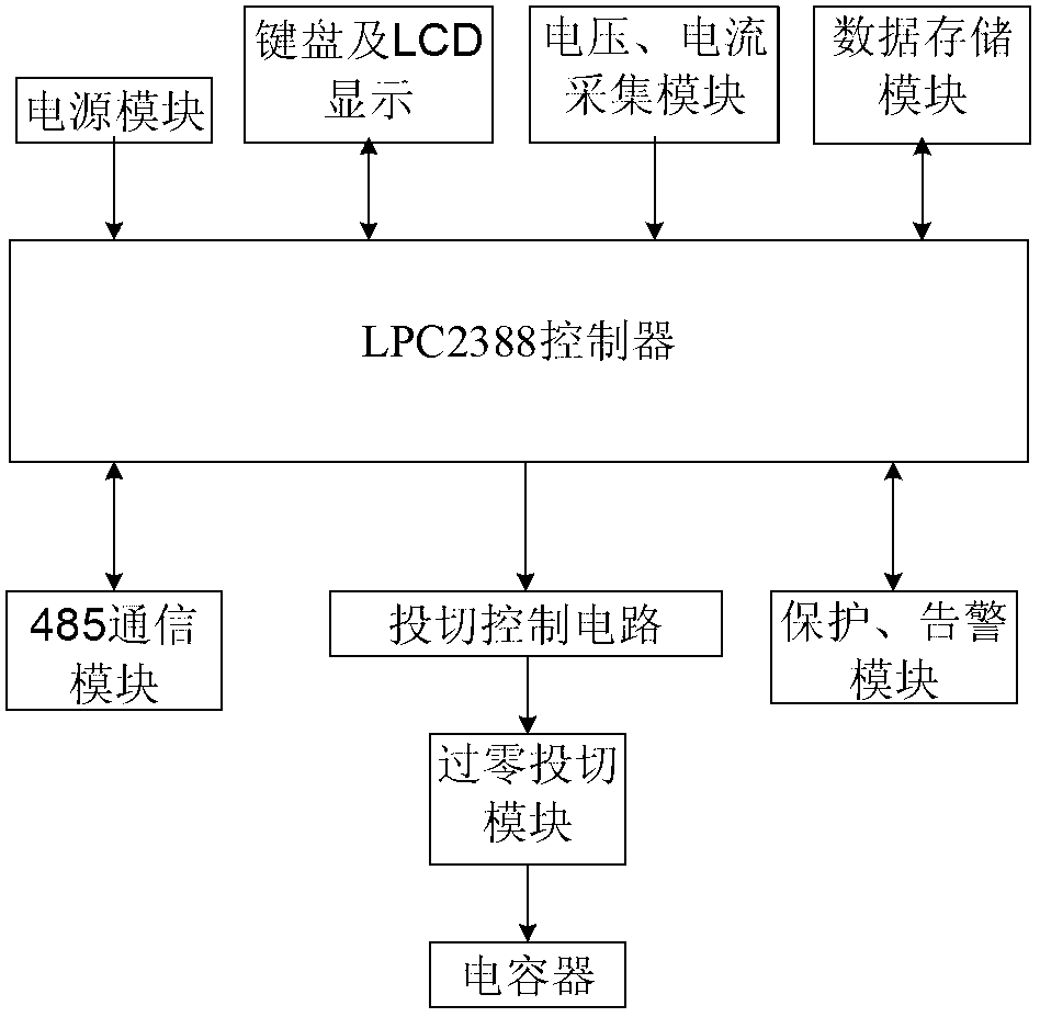
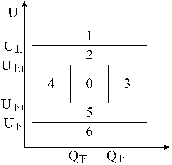
[0044] This embodiment proposes an intelligent low-voltage reactive power compensation device, which is composed of a control circuit and a capacitor. Considering the difference between the detection index and the direct control quantity of the power supply system, the present invention simultaneously considers voltage, power factor and reactive power, as a control Basis for capacitor switching.

[0045] This embodiment provides a control circuit for a low-voltage reactive power compensation device. The reactive power compensation device includes a capacitor. In a device whose working mode is three-phase compensation, the capacitor is connected in a star connection; a device whose working mode is three-phase compensation Among them, the capacitor is connected in delta shape. Its control part is as figure 1As shown, it ...


PUM


Abstract

The invention provides a control circuit of a low-voltage reactive compensation device. The control circuit of the low-voltage reactive compensation device comprises a control module, a power supply module, an HCI (Human-Computer Interaction) module, a collection module, a data storage module, a communication module, a switching control circuit, a zero passage switching module and a protection alarm module, wherein the control module is respectively connected with the power supply module, the HCI module, the collection module, the data storage module, the communication module, the switching control circuit and the protection alarm module, and the switching control circuit is sequentially connected with the zero passage switching module and a capacitor. A distribution network system is partitioned according to a voltage value and a reactive power value, the existing nine-zone diagram is improved, and a reactive compensation device can be compensated by a controller according to the improved nine-zone diagram. According to the control circuit disclosed by the invention, the problem that frequent switching is easy to cause in the traditional nine-zone diagram control is overcome, and the control circuit has the advantages that the cost is low, the application is flexible, and the fast and accurate switching of the capacitor can be realized.

Description

technical field [0001] The invention relates to the field of power grid reactive power compensation, in particular to a control circuit of a low-voltage reactive power compensation device and a control method thereof. Background technique [0002] In industrial production and daily life, most loads are resistive and inductive, which consume a lot of reactive power. The transmission of reactive power in the transmission line will cause the current in the line to increase, thereby increasing the loss in the line. At the same time, it will also cause a drop in voltage quality, which will adversely affect electrical equipment. Therefore, the application of reactive power compensation device plays an important role in improving the power factor of the system and the quality of transmission voltage, which is conducive to the efficient and safe operation of the power grid, and is also of great significance for energy saving and emission reduction. [0003] At present, the common ...

Claims


Application Information

Patent Timeline
IPC IPC(8): H02J3/18
CPCY02E40/30
Inventor 高春雷丁孝华田小锋王丙文王双虎杨宇峰张晓燕席旸旸
Owner CHINA ELECTRIC POWER RES INST
Why Eureka
Try Eureka