
Hinge

A technology of hinges and components, applied in the field of hinges, can solve problems such as unpredictable braking torque

Active Publication Date: 2012-10-10
DR SCHNEIDER KUNSTWERKE
View PDF12 Cites 6 Cited by
  • Summary
  • Abstract
  • Description
  • Claims
  • Application Information

AI Technical Summary

Problems solved by technology

In addition, with known hinges it is not possible to predetermine the braking torque

Method used


Image

  • Hinge
  • Hinge
  • Hinge

Examples


Embodiment Construction

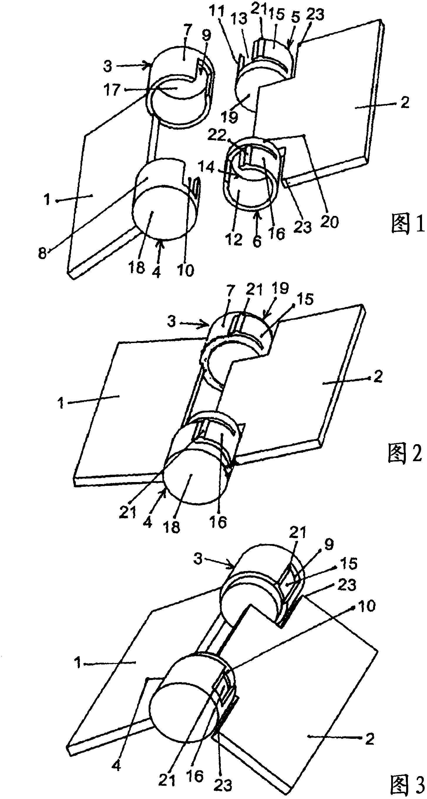
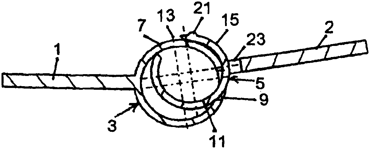
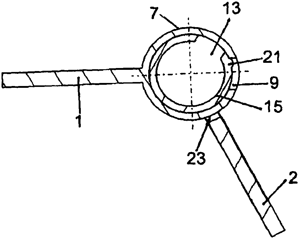
[0032] All of the figures show that the first plastic component 1 is provided with shaped joint elements 3, 4, each of which is formed by a bearing bushing 7, 8, each bearing bushing having a closed bottom surface arranged on opposite sides 17, 18 and longitudinal slots 9, 10 extending to the bottom. The longitudinal slots 9 , 10 are arranged approximately opposite the fastening sides of the first hinge elements 3 , 4 on the first component 1 . In this case, the first component is a plastic molded part produced by injection molding, wherein the joint elements 3 , 4 are molded together. Corresponding exactly to these bearing sleeves 7 , 8 , second hinge elements 5 , 6 are arranged on the second component 2 , each second hinge element is formed as an insertion sleeve 11 , 12 and has a closed bottom surface 19 , 20 each, each The bottom faces are fastened oppositely to the second component 2 in such a way that a guide opening 23 is produced between the housing wall and the secon...


PUM


Abstract

The present invention relates to a hinge for the swivelling connection of two components (1, 2), made of at least one first round hinge element (3, 4) on the first component (1) and at least one corresponding second round hinge element (5, 6) on the second component (2), wherein said hinge elements (3, 5; 4, 6) are connected to one another such that they can rotate around the centre axis. The first hinge element (3, 4) is a bearing sleeve (7, 8) having a longitudinal gap, over which an insertion sleeve (11, 12), likewise provided with a longitudinal gap (13, 14), can be completely screwed in as a second hinge element (5, 6).

Description

technical field [0001] The invention relates to a hinge for connecting two members for pivotal movement, comprising at least one circular first hinge element on a first member and at least one corresponding circular first hinge element on a second member. Two hinge elements are rotatably connected to each other around the central axis. Background technique [0002] A hinge articulates the two planes on one edge. Hinges are designed as joints to connect two members to each other. Hinges, for example on doors or container lids, are used to open or close correspondingly covered spaces. There are hinges that can withstand high loads in terms of weight and have correspondingly strong hinges and pins that connect the swivel joints to one another. In addition, plastic hinges are used, in particular for connecting lightweight components, which are light, can be produced in large quantities inexpensively, and can be used simply or co-injected as film hinges between the plastic par...

Claims


Application Information

Patent Timeline
Patent Type & Authority Applications(China)
IPC IPC(8): E05D1/04E05D1/06E05D11/08E05D11/10
CPCE05D1/06E05D11/105E05Y2201/632E05D11/082E05D1/04E05Y2800/342E05D11/06
Inventor J·施耐德
Owner DR SCHNEIDER KUNSTWERKE
Learn More