
Machine room elevator speed limiter

An elevator speed limiter and organic technology, applied in elevators, transportation and packaging, etc., can solve problems such as hidden safety hazards, inability to remotely realize manual triggering of braking, etc., to achieve the effect of increasing safety and reducing occupied space

Active Publication Date: 2018-08-03
SUZHOU PROTEC AUTO-CONTROL TECH CO LTD
View PDF6 Cites 3 Cited by
  • Summary
  • Abstract
  • Description
  • Claims
  • Application Information

AI Technical Summary

Problems solved by technology

[0002] The elevator speed limiter is one of the safety control components in the elevator safety protection system. When the elevator is running for any reason, the car may overspeed or even fall, and all other safety protection devices do not work. If the overspeed limiter and the safety gear are in a linkage action, the elevator car will be stopped. However, the current elevator cannot remotely realize the functions of manual trigger braking and manual reset braking during running detection, and requires short-distance operation. can cause many safety hazards

Method used


Image

  • Machine room elevator speed limiter
  • Machine room elevator speed limiter
  • Machine room elevator speed limiter

Examples


Embodiment Construction

[0024] The present invention will be further described below in conjunction with the accompanying drawings and specific embodiments.

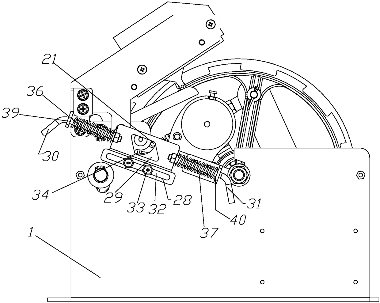
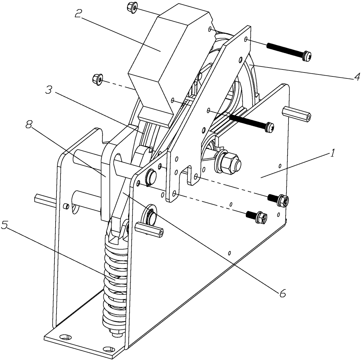
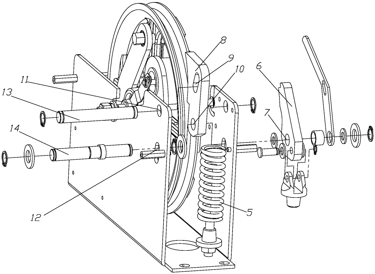
[0025] Such as Figure 1 to Figure 3 The machine-room elevator speed limiter shown includes a bracket 1, and a speed limiter switch 2 is installed on the upper part of the bracket 1. The bracket 1 includes a bottom plate and a side wall, and a sheave assembly is arranged inside the bracket 1, and the sheave assembly It includes a sheave mechanism 3 and a ratchet mechanism 4 for winding the wire rope, the sheave assembly is provided with a brake assembly on one side, and also includes a block assembly 15 hinged on the side wall for triggering the brake assembly to work , the said sheave mechanism 3 is also provided with a pituitary assembly that drives the rotation of the block assembly 15, and one side of the block assembly is provided with a drive rod 21 protruding from the side plate, and also includes a mechanical trigger reset that drives t...


PUM


Abstract

The invention discloses a machine room elevator speed limiter which comprises a support. A speed limiter switch is mounted on the upper portion of the support. A rope wheel assembly is arranged in thesupport. A brake assembly is arranged on one side of the rope wheel assembly. The machine room elevator speed limiter further comprises a stop block assembly hinged to the side wall and used for triggering the brake assembly to work. Overhang assemblies for driving the stop block assembly to rotate are further arranged in the rope wheel assembly. A drive rod stretching out of a side plate is arranged on one side of the stop block assembly. The machine room elevator speed limiter further comprises a mechanical trigger reset mechanism for driving the drive rod to move. According to the machineroom elevator speed limiter, during brake detection, even though the speed limiter does not exceed the limited speed, remote trigger, reset and other operation can be carried out in a manner of manually pulling a brake cable, and therefore a worker does not need to approach to the speed limiter for operation, and safety during brake detection is increased.

Description

technical field [0001] The invention relates to a speed governor for an elevator, in particular to a machine room elevator speed governor. Background technique [0002] The elevator speed limiter is one of the safety control components in the elevator safety protection system. When the elevator is running for any reason, the car may overspeed or even fall, and all other safety protection devices do not work. If the overspeed limiter and the safety gear are in a linkage action, the elevator car will be stopped. However, the current elevator cannot remotely realize the functions of manual trigger braking and manual reset braking during running detection, and requires short-distance operation. It will cause many safety hazards. Contents of the invention [0003] The technical problem solved by the invention is to provide a machine room elevator speed limiter that can realize remote triggering and reset. [0004] The technical solution adopted by the present invention to sol...

Claims


Application Information

Patent Timeline
Patent Type & Authority Applications(China)
IPC IPC(8): B66B5/00B66B5/04
CPCB66B5/0093B66B5/048Y02B50/00
Inventor 本村和彦胡永刚
Owner SUZHOU PROTEC AUTO-CONTROL TECH CO LTD
Learn More