Eureka AIR delivers breakthrough ideas for toughest innovation challenges, trusted by R&D personnel around the world.

Auto oil injector cleaning connector

A technology of fuel injectors and connectors, which is applied in the direction of machines/engines, engine components, mechanical equipment, etc., and can solve problems such as unsafe operation and complexity

Inactive Publication Date: 2012-10-17
何秋生
View PDF0 Cites 0 Cited by
  • Summary
  • Abstract
  • Description
  • Claims
  • Application Information

AI Technical Summary

Problems solved by technology

[0002] Currently on the market, the cleaning of automobile fuel injectors uses a special cleaning tool (commonly known as a hanging bottle). As reported by Xu Wenjian in the announcement of the China Patent Office in 2003, the authorized announcement number is CN2665377, and the patent number 20030106228. Oil nozzle cleaning device), the utility model patent and the technical scheme adopted, it effectively solves the purpose of cleaning the oil nozzle without dismantling, but this method still has shortcomings. Cleaning agent, pouring into stainless steel tank is unsafe and complicated to operate

Method used


Image

  • Auto oil injector cleaning connector
  • Auto oil injector cleaning connector
  • Auto oil injector cleaning connector

Examples


Embodiment Construction

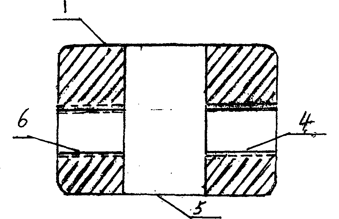
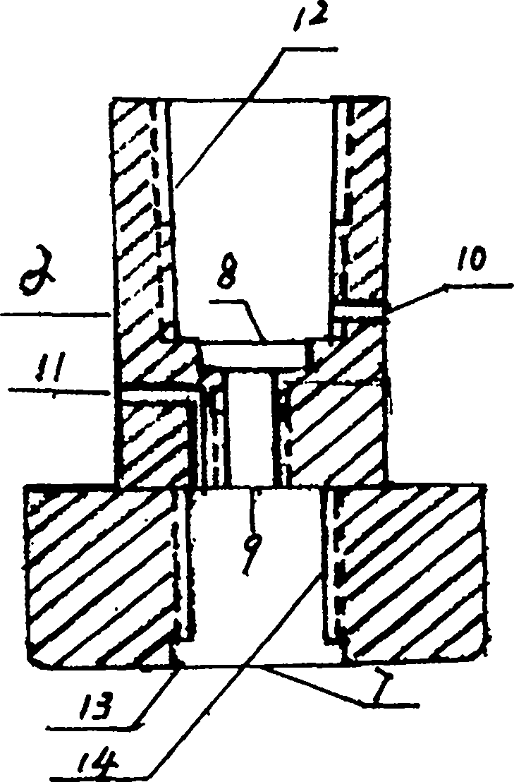
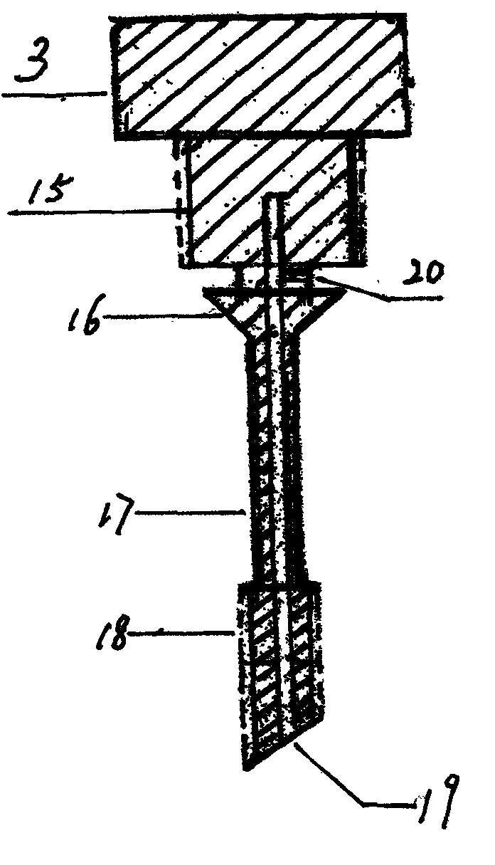
[0005] The embodiment of the automotive fuel injector cleaning connector invented by the utility model: the valve core (2) is pressed into the valve seat (1) to tightly fit into the connection hole (5), and one side of the valve seat (1) is connected to the pressure gauge (4) , the other side is connected to the intake switch (6), the valve needle (3) enters the valve core (2) through the connecting thread (12), the front end (18) of the valve needle (3) is threaded to the valve core (9), and the oil injection Nozzle cleaner product connection thread (14), turn the front end (18) of the needle valve (3) to open the product sealing valve, the air enters the spool channel (19) from the air intake channel (10), and enters the nozzle cleaner product bottle , at the same time, the needle valve (16) seals the sealing hole (8), the air intake channel (20) is separated from the solution outlet (11), and because the air intake channel is higher than the solution outlet, the air pressure...


PUM


Abstract

An auto oil injector cleaning connector is classified into the mechanical engineering part according to the international patent classification (IPC). The auto oil injector cleaning connector is characterized in that: a stainless steel container is canceled on the basis of the original tool, which saves cost and material; when a factory produces an oil injector cleaning agent, a disposable sealing valve can be adopted without increasing the cost and transportation and storage are safer compared with a previous product; and the product is directly mounted on the auto oil injector cleaning connector, the cleaning agent does not need to be poured into the container, operation procedures are reduced and therefore safety, speed and strong practicability are promoted. The auto oil injector cleaning connector is simple to manufacture and has low cost. The auto oil injector cleaning connector comprises three parts of a valve seat, a valve core and a needle valve. The front end of the valve core is proved with a connecting thread of the oil injector cleaning agent product. An air inlet passage and the solution outlet are separated up and down. The air inlet passage is provided with a sealing hole. The front end of the needle valve can open the oil injector cleaning agent product to have the valve sealed, and the rear end of the needle valve seals the air inlet passage. Air through the air inlet passage of the needle valve is pressed into an oil injector cleaning agent tank. Air pressure makes the oil injector cleaning agent flow out from the solution outlet. During the whole cleaning process, an engine runs smoothly and operation is completed in one time and the connector can be promoted.

Description

(1): technical field [0001] Automotive fuel injector cleaning connector: according to the International Patent Classification (IPC), it belongs to the Department of Mechanical Engineering. Engines or pumps division; Combustion engines, engines of heat or combustion products class; Piston internal combustion engines, combustion engines in general subclass; Components, parts or accessories not included in other classes: Cleaning of combustion engines , anti-corrosion or anti-erosion or prevention of harmful deposits. (two) background technology: [0002] At present, the cleaning of automobile fuel injectors on the market uses a special cleaning tool (commonly known as a hanging bottle). As reported by Xu Wenjian in the announcement of the China Patent Office in 2003, the authorized announcement number is CN2665377, and the patent number 20030106228. Oil nozzle cleaning device), the utility model patent and the technical scheme adopted, it effectively solves the purpose of cle...

Claims


Application Information

Patent Timeline
IPC IPC(8): F02B77/04
Inventor 何秋生
Owner 何秋生
Why Eureka
Eureka Blog
Learn More