Rotary heat exchange element

A heat exchange element and rotary technology, which can be used in household heating, heating methods, household heating, etc., and can solve problems such as failure to achieve filtering functions

Inactive Publication Date: 2012-10-17
SHERPACNC +1
View PDF7 Cites 5 Cited by
  • Summary
  • Abstract
  • Description
  • Claims
  • Application Information

AI Technical Summary

Problems solved by technology

The problem with these heat exchange elements is that they cannot perform a substantially effective filtering function of the outside air supplied to the room.

Method used


Image

  • Rotary heat exchange element
  • Rotary heat exchange element
  • Rotary heat exchange element

Examples


Embodiment Construction

[0026] Hereinafter, the present invention will be described in detail with reference to the drawings.

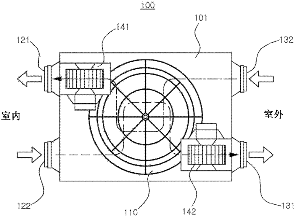
[0027] figure 1 It is a configuration diagram for explaining a heat exchanger using a heat exchange element according to an embodiment of the present invention.

[0028] refer to figure 1 , the heat exchanger 100 involved in this embodiment may include: a main body shell 101, which is formed with an air inlet and an exhaust port; a plurality of blowing fans 141, 142, arranged inside the main body shell 101; and heat exchange elements 110.

[0029] The front surface and the rear surface of the main body case 101 may be respectively formed with air suction ports 122, 132 through which air is sucked in, and discharge ports 121, 131 through which the sucked air is discharged. That is, an indoor air inlet 122 for sucking in indoor air and an indoor air outlet 121 for discharging air sucked in from the outside into the room may be formed on the front surface of the main body ca...


PUM


Abstract

The invention provides a rotary heat exchange element which is provided with a first path which enables the indoor air to flow to the outside and a second path which enables the outdoor air to flow to the inside. The heat exchange element includes a first outer layer, a second outer layer, and a middle layer. The first outer layer includes one area which is corresponding to the first path and the other area which is corresponding to the second path. The second outer layer includes one area which is corresponding to the first path and the other area which is corresponding to the second path, and the second outer layer is opposite to the first outer layer. The middle layer includes an activated carbon filter layer where the activated carbon is deposited, and the activated carbon filter layer is arranged between the first outer layer and the second outer layer and is used for filtering the outdoor air passing through the second outer layer to the first outer layer and the outdoor air passing through the first outer layer to the second outer layer. The heat exchange element absorbs the sensible heat and the latent heat of the indoor air which flows into one area of the first outer layer, and transmits the sensible heat and the latent heat to the outdoor air which flows into the other area of the second outer layer.

Description

[0001] technology area [0002] The invention relates to a rotary heat exchange element (ROTARY TYPE HEAT EXCHANGING APPARATUS), in particular to a rotary heat exchange element performing heat exchange and air filtration functions. Background technique [0003] Modern life is bound to be accompanied by living indoors isolated from outdoor air, and therefore, a ventilation device for exchanging indoor air with outdoor air is essential. Common indoor ventilation devices utilize blowers to discharge indoor air to the outside. However, when the indoor air is discharged in this way, while the cold or hot air in the room is discharged to the outside without being filtered, the air outside the room flows into the room through the window or the crack of the door, thus losing the air that has been cooled or heated in the room. Heat, resulting in unnecessary consumption of cooling or heating costs. [0004] In order to solve such problems, a waste heat recovery ventilation device is p...

Claims


Application Information

Patent Timeline
Patent Type & Authority Applications(China)
IPC IPC(8): F24F13/30F24F13/28
CPCY02P80/15F24F3/1411F24F12/006F24F13/28F24F2203/104F24F2203/108Y02B30/56
Inventor 金熙植
Owner SHERPACNC
Why Eureka
Try Eureka