
Method for fabricating flexible substrate LCD (liquid crystal display) and flexible substrate LCD

A technology of flexible substrates and manufacturing methods, applied in nonlinear optics, instruments, optics, etc., can solve the problems of uneven distribution, uneven thickness of LCD boxes, etc., and achieve the effect of solving uneven thickness of boxes

Inactive Publication Date: 2012-10-17
陈国平
View PDF6 Cites 10 Cited by
  • Summary
  • Abstract
  • Description
  • Claims
  • Application Information

AI Technical Summary

Problems solved by technology

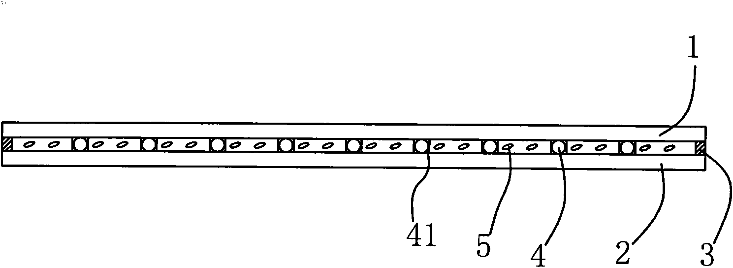
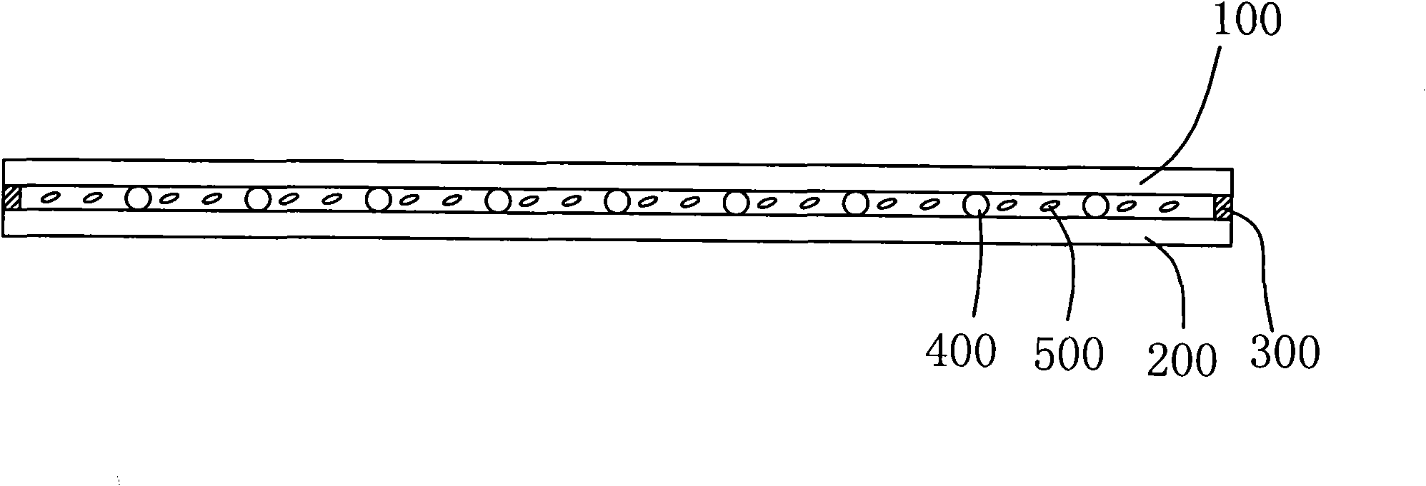
[0004] In the above-mentioned LCD production process, the filling process generally adopts vacuum filling. When the vacuum filling atmosphere is opened, the atmospheric pressure is simultaneously pressurized on the upper and lower substrates. Since the substrates are in a vacuum state, the liquid crystal between the substrates is affected by the atmospheric pressure. In the process of rapid diffusion, the liquid crystal will have a certain impact force on the spherical spacer during the rapid diffusion process. This impact force will make the spherical spacer with weaker fixation force move with the liquid crystal flow direction, resulting in a spherical spacer. The spacer is unevenly distributed between the two substrates. Where there is no spherical spacer, the two substrates are concave by 600, and where the spherical spacer is piled up, the two substrates are raised by 700, resulting in uneven thickness of the LCD box (such as Figure 4 shown), when displayed, there will be bright or dark spots on the display
This phenomenon is particularly prominent in LCDs with flexible substrates, that is, LCDs that include at least one flexible substrate

Method used


Image

  • Method for fabricating flexible substrate LCD (liquid crystal display) and flexible substrate LCD
  • Method for fabricating flexible substrate LCD (liquid crystal display) and flexible substrate LCD
  • Method for fabricating flexible substrate LCD (liquid crystal display) and flexible substrate LCD

Examples


Embodiment Construction

[0023] The invention provides a method for manufacturing a flexible substrate LCD, comprising a flexible upper substrate and a flexible lower substrate with transparent electrodes, including the following steps,

[0024] (1), alignment film manufacturing step, make alignment film on the transparent electrode of flexible upper substrate and flexible lower substrate respectively; The making of alignment film can adopt conventional method, promptly on the transparent electrode of flexible upper substrate and flexible lower substrate Coat the orientation film separately, and after curing, use a rubbing cloth for orientation treatment;

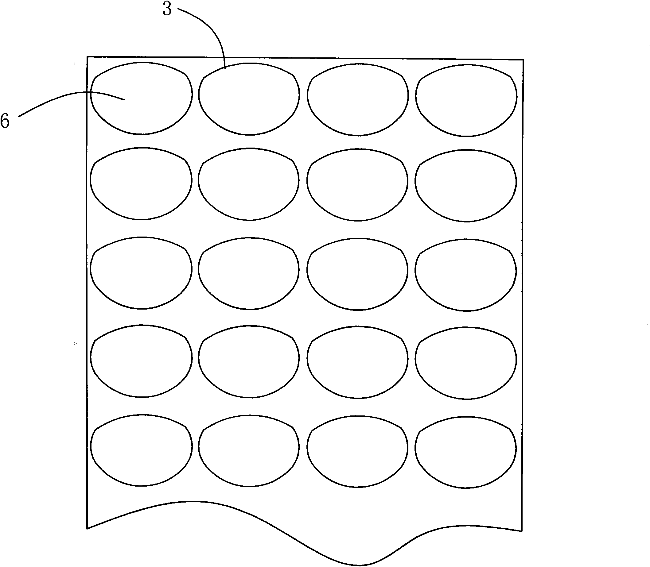
[0025] (2), the step of printing spacers, printing rubber particles on the flexible upper substrate or the flexible lower substrate, and at least one spherical spacer is contained in each of the rubber particles; the specific method of printing the spacers is, first Many hemispherical pits are evenly arranged on the printing roller, and spherical s...


PUM


Abstract

The invention discloses a method for fabricating a flexible substrate LCD (liquid crystal display) and the flexible substrate LCD. The fabricating method comprises the following steps of an alignment film fabricating step, a spacer printing step of printing colloidal particles on an upper flexible substrate or a lower flexible substrate, a frame sealing glue printing step of printing frame sealing glue with a predetermined shape on the upper flexible substrate or the lower flexible substrate and reversing a crystal pouring port, a substrate cladding and curing step, and a crystal pouring and sealing step, wherein each colloidal particle at least includes one globular spacer. The globular spacer and the flexible substrate surface are printed on the colloidal particles, and the upper and the lower flexible substrates are fixed together with the frame sealing glue when cladding the plate, so that the globular spacer is located in the colloidal particle and firmly connected with the upper and the lower flexible substrates, even when the liquid crystal rapidly diffuses, the phenomenon that the globular spacer is washed away due to the inefficient adhesive force can be avoided, and the problem of the irregular thickness of the LCD display screen is solved.

Description

technical field [0001] The invention relates to a manufacturing method of a flexible substrate LCD and the flexible substrate LCD. Background technique [0002] Existing LCDs generally include an upper substrate 100 and a lower substrate 200. The upper substrate 100 and the lower substrate 200 are fixedly connected by a sealant 300. In order to ensure a certain thickness of the box, a spacer is provided between the lower substrate 100 and the lower substrate 200. The spacer 400 is filled with a liquid crystal material 500 in the remaining space after removing the space occupied by the spacer 400 (see image 3 ). [0003] The common practice of this LCD is to spray the spacer 400 (mostly spherical spacers) evenly on the surface of the substrate on the surface of the upper substrate 100 or the lower substrate 200 by spraying, On one side of the surface, use the printing method to print the sealant 300, reserve the opening for the crystal filling, and attach the side of the tw...

Claims


Application Information

Patent Timeline
IPC IPC(8): G02F1/1339G02F1/1333G02F1/1335
Inventor 陈国平
Owner 陈国平
Learn More