
System and method for wireless measurement of detection instrument

A detection instrument and wireless measurement technology, which is applied in the field of industrial detection, can solve the problems of inability to obtain the data of the detection instrument, the inability to obtain data in real time, and the inconvenience of using portable instruments.

Inactive Publication Date: 2014-05-21
北京时代之峰佳亿科技有限责任公司
View PDF3 Cites 0 Cited by
  • Summary
  • Abstract
  • Description
  • Claims
  • Application Information

AI Technical Summary

Problems solved by technology

[0006] Due to the need to frequently collect data and then manually transfer the data, the shortcomings of method 1 are mainly reflected in: on the one hand, it is very cumbersome, and on the other hand, it cannot obtain data in real time;
[0007] Due to the need to use a wired network, the shortcomings of the second method are mainly reflected in: the data of the testing instrument cannot be obtained using wireless devices such as tablet computers and PDAs
In addition, the wired network transmission method will also bring inconvenience to users in the application of portable instruments.

Method used


Image

  • System and method for wireless measurement of detection instrument
  • System and method for wireless measurement of detection instrument
  • System and method for wireless measurement of detection instrument

Examples


Embodiment Construction

[0028] The following will clearly and completely describe the technical solutions in the embodiments of the present invention with reference to the accompanying drawings in the embodiments of the present invention. Obviously, the described embodiments are only some, not all, embodiments of the present invention. Based on the embodiments of the present invention, all other embodiments obtained by persons of ordinary skill in the art without making creative efforts belong to the protection scope of the present invention.

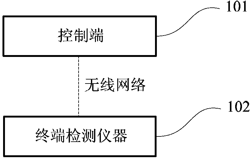
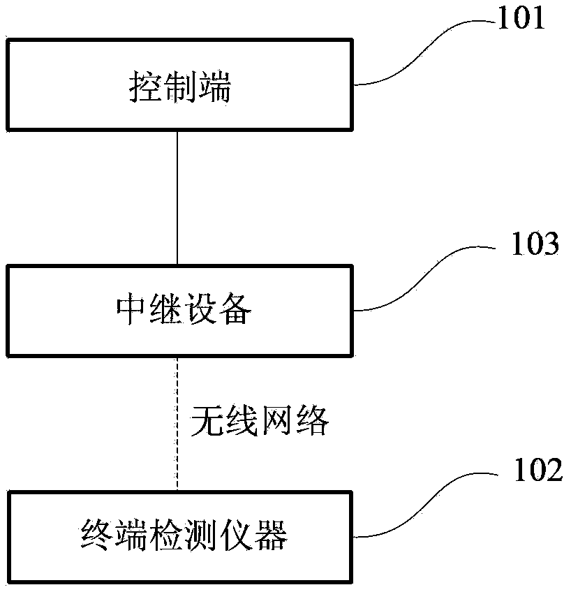
[0029] figure 1 , figure 2 It is a schematic structural diagram of the wireless measurement system of the detection instrument provided by the present invention. As shown in the figure, the wireless measurement system of the testing instrument includes: a control terminal 101 and a terminal testing instrument 102, and the control terminal 101 and the terminal testing instrument 102 communicate in a wireless manner.

[0030] Specifically, the control termina...


PUM


Abstract

The invention provides a system and a method for wireless measurement of a detection instrument. The system for wireless measurement of the detection instrument comprises a control terminal and a terminal detection instrument, wherein the control terminal wirelessly communicates with the terminal detection instrument. According to the technical scheme, on the one hand, the instrument detection data can be acquired, and on the other hand, the instrument detection data can also be acquired by wireless equipment.

Description

technical field [0001] The present invention relates to the technical field of industrial testing, in particular to a wireless measuring system and method for industrial testing instruments. Background technique [0002] Existing industrial testing instruments generally interact with the data processing end in the following two ways: [0003] Method 1: In the industrial field environment, directly use testing instruments (such as: Leeb hardness tester) to collect hardness data, and then transfer and store the hardness data to the data processing terminal through mobile storage devices such as U disk; [0004] Method 2: In an industrial field environment, use a wired network to connect a testing instrument (such as a Leeb hardness tester) to a data processing terminal. [0005] However, both of the above formulas have obvious defects: [0006] Due to the need to frequently collect data and then manually transfer the data, the shortcomings of method 1 are mainly reflected in...

Claims


Application Information

Patent Timeline
Patent Type & Authority Patents(China)
IPC IPC(8): G08C17/02
Inventor 杨长江
Owner 北京时代之峰佳亿科技有限责任公司
Learn More