Complete online monitoring device of relay protection outlet circuit

A relay protection and monitoring device technology, applied in measuring devices, measuring electricity, measuring electrical variables, etc., can solve problems such as loss, circuit failure, and inability to send out, and achieve widespread promotion and use significance, improve reliability, and reasonable design. Effect

Active Publication Date: 2012-10-24
STATE GRID TIANJIN ELECTRIC POWER +1
View PDF4 Cites 12 Cited by
  • Summary
  • Abstract
  • Description
  • Claims
  • Application Information

AI Technical Summary

Problems solved by technology

[0006] From the above, it can be seen that since the "control circuit disconnection" signal is only composed of the normally closed contact of TWJ and the normally closed contact of HWJ in series, and the HWJ relay can only reflect whether the circuit between the 4X22-06 terminal and -KM in the trip circuit is conductive. TWJ can only reflect whether the circuit between terminal 13 of QF-1 and -KM in the closing circuit is connected. If there is a disconnection in the above-mentioned part, the "control circuit disconnection" signal cannot be issued. Therefore, in the protection exit circuit, except The loop outside the above part is the "blind spot" of online monitoring
[0007] If the circuit is blocked in the "blind spot", it will cause failure to trip and close
The "blind spot" of this monitoring is composed of power secondary cables, terminal blocks, and pressure plates. The intuitive message alarm can only be found when the switch needs to be tripped and closed, which may cause the switch to refuse to move, the accident will expand, cause the power grid accident and cause major economic losses

Method used


Image

  • Complete online monitoring device of relay protection outlet circuit
  • Complete online monitoring device of relay protection outlet circuit
  • Complete online monitoring device of relay protection outlet circuit

Examples


Embodiment Construction

[0021] The embodiments of the present invention will be described in further detail below in conjunction with the accompanying drawings: It should be emphasized that the embodiments of the present invention are illustrative rather than restrictive, and should not limit the protection scope of the present invention.

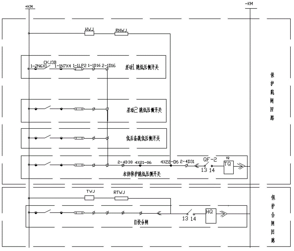
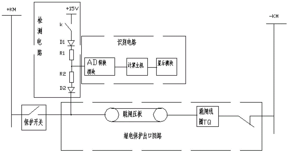
[0022] A complete on-line monitoring device for a relay protection outlet circuit, including an on-line detection and identification circuit connected between each relay protection switch and a tripping pressure plate, each detection and identification circuit includes a detection circuit and an identification circuit, and the detection circuit One end is a power supply, and an electronic switch K, a high-voltage diode D1, a current-limiting resistor R1, a current-limiting resistor R2, and a high-voltage diode D2 are connected in series from the power supply to the node of the relay relay protection switch and the tripping pressure plate; the identification circuit ...


PUM


Abstract

The invention relates to a complete online monitoring device of a relay protection outlet circuit. The complete online monitoring device comprises online detection and identification circuits connected between each path of relay protection switch and a tripping pressure plate, wherein each detection and identification circuit comprises a detection circuit and an identification circuit, a power supply is arranged at one end of the detection circuit, and an electronic switch K, a high-voltage diode D1, a current limiting resistor R1, a current limiting resistor R2 and a high-voltage diode D2 are in serial connection from the power supply to nodes of the relay protection switch and the tripping pressure plate in sequence; and the identification circuit comprises an AD (analog-to-digital) conversion module, a computer mainframe and a display module, wherein one end of the AD conversion module is connected to a node between the current limiting resistor R1 and the current limiting resistor R2, the other end of the AD conversion module is connected with the computer mainframe, and the computer mainframe is also connected with the display module. By installing the monitoring device disclosed by the invention in a substation, the circuit can be completely monitored in real time through LED (light emitting diode) display and signals uploaded by an RS485 (recommended standard 485) communication bus, so that the system reliability can be improved.

Description

technical field [0001] The invention belongs to the technical field of electric power system relay protection, and in particular relates to an online complete monitoring device for a relay protection outlet circuit. Background technique [0002] The currently used relay includes a protection trip circuit and a protection closing circuit. Taking the main switch on the low-voltage side as an example, the protection trip circuit includes a differential 1-jump low-voltage side switch, a differential 2-jump low-voltage side switch, and a low-voltage side switch. The back-up tripping low-voltage side switch and the main body protection tripping low-voltage side switch circuit are self-injection closing circuits in the protection closing circuit. The auxiliary contacts of the relay are divided into two types: normally open (moving close) and normally closed (moving break). Depend on figure 1 As shown, the normally closed contact QF-1 is introduced into the closing circuit, and th...

Claims


Application Information

Patent Timeline
Patent Type & Authority Applications(China)
IPC IPC(8): G01R31/02
Inventor 李建伟
Owner STATE GRID TIANJIN ELECTRIC POWER
Why Eureka
Try Eureka