Construction method of flow field numerical model in minimum quantity lubrication cutting area

A technology of minimum quantity lubrication and numerical model, which is applied in the field of mechanical cutting, can solve the problems affecting the simulation results, and the public report of the numerical model of the flow field in the cutting zone of the minimum quantity lubrication has not been found.

Active Publication Date: 2012-10-24
SHANGHAI SMARTSTATE TECH CO LTD
View PDF2 Cites 16 Cited by
  • Summary
  • Abstract
  • Description
  • Claims
  • Application Information

AI Technical Summary

Problems solved by technology

Moreover, the DPM model has different conditions from the two-phase flow in the boundary setting, so the appropriate flow field model will affect the simulation results
[0

Method used


Image

  • Construction method of flow field numerical model in minimum quantity lubrication cutting area
  • Construction method of flow field numerical model in minimum quantity lubrication cutting area
  • Construction method of flow field numerical model in minimum quantity lubrication cutting area

Examples


Embodiment Construction

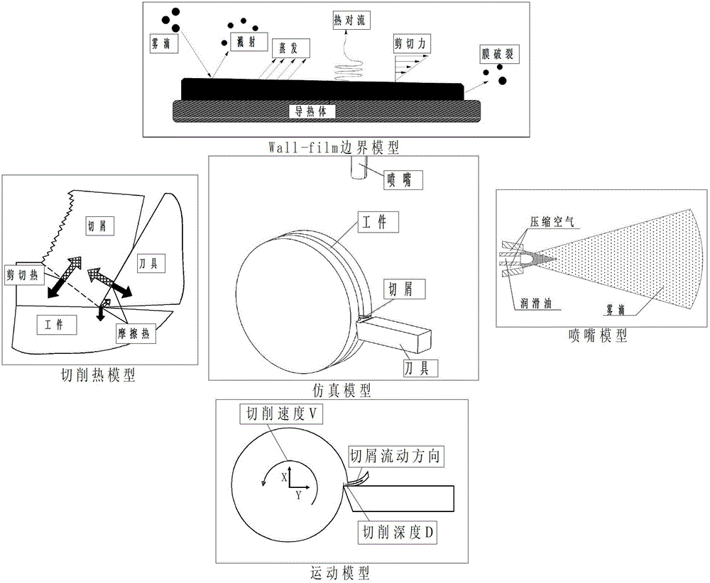
[0022] The method for constructing the numerical model of the flow field in the MQL cutting zone of the present invention combines four factors that will affect the MQL in the cutting zone during the cutting process: the relative motion between the workpiece and the tool, the cutting heat generation during the cutting process, the boundary model and The DPM model suitable for minimum quantity lubrication is added to the simulation model to simulate the cutting process to the greatest extent, and by changing the input parameters of the simulation, the flow field distribution of the minimum quantity lubrication cutting area under different cutting parameters and lubrication parameters can be simulated. It includes the following steps:

[0023] The first step is to establish a two-dimensional or three-dimensional cutting model, which includes nozzles, workpieces, tools and chips.

[0024] The second step is to divide the established cutting two-dimensional or three-dimensional mo...


PUM


Abstract

A construction method of a flow field numerical model in a minimum quantity lubrication cutting area comprises the following steps of building a cutting two-dimensional or three-dimensional model; conducting grid dividing on the module; leading the grid-dividing-completed-model in simulation software and using a steady state flow field computing method to conduct simulation after defining entry conditions and exit conditions; building a motion model and a cutting heat model and converting the motion model and the cutting heat model into recognizable language of the simulation software; selecting an appropriate nozzle model and a wall film boundary model; leading the models in a steady state flow field and using an unsteady state computing method to conduct simulation to obtain velocity field distribution, pressure field distribution, temperature field distribution, fogdrop diameter and fogdrop speed. The construction method can have flow field influences of minimum quantity lubrication on the cutting area during cutting and influences on the minimum quantity lubrication on workpieces and temperature fields inside a tool, provides basis for minimum quantity lubrication system setting, and simultaneously is used for parameter optimization of a minimum quantity lubrication system.

Description

technical field [0001] The invention relates to a lubrication method for cutting processing, in particular to a method for constructing a numerical model of a flow field in a cutting zone of a minimum quantity lubrication (Minimum Quantity Lubrication), and belongs to the technical field of mechanical cutting processing. Background technique [0002] Minimal quantity lubrication cutting technology usually refers to a lubrication method in which compressed air carries lubricating oil broken into microns by compressed air into the cutting area. The lubricating oil mist forms a lubricating film between the workpiece and the tool to reduce the friction between the tool and the workpiece, and the compressed air absorbs heat through heat exchange and the lubricating oil evaporates, so the temperature in the cutting area can be reduced and the tool size can be reduced. Wear and improve cutting performance. However, many problems still need to be solved in the research and practica...

Claims


Application Information

Patent Timeline
IPC IPC(8): G06F17/50G06T17/00
Inventor 陈明姜立刘志强安庆龙
Owner SHANGHAI SMARTSTATE TECH CO LTD
Why Eureka
Try Eureka