Cutting insert
A cutting tool and inserting technology, applied in the direction of milling cutter, forming knife, optics, etc., can solve the problems of insufficient cutting edge strength and non-existence, and achieve the effect of optimizing force deflection and firm positioning
- Summary
- Abstract
- Description
- Claims
- Application Information
AI Technical Summary
Problems solved by technology
Method used
Image
Examples
Embodiment Construction
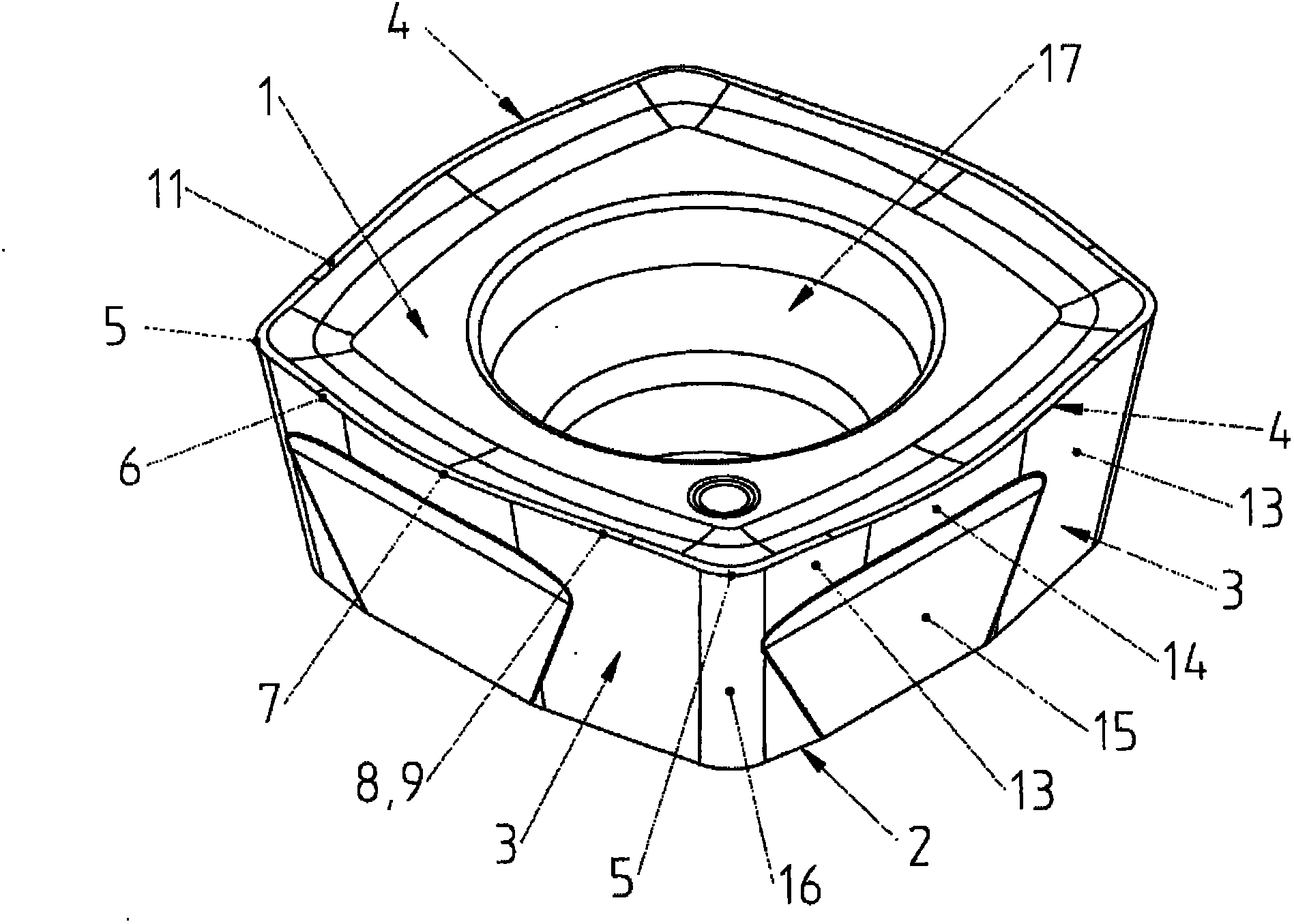
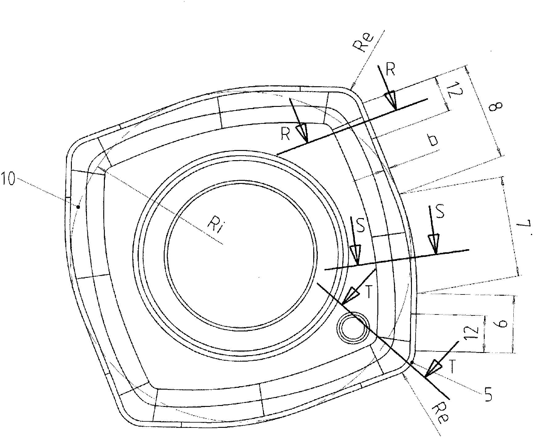
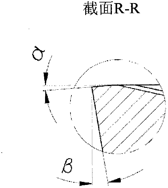
[0024] figure 1 and figure 2 , respectively a perspective view and a plan view, showing an insert cutting tool according to the invention having a square basic shape. The plunger cutting tool has a top face 1 , a bottom face 2 and a raised side face 3 inclined relative to the top face 1 at a clearance angle β. A raised cutting edge 4 is formed at the intersection between the top face 1 and the side face 3 . Each cutting edge 4 has a straight wiper edge 6 adjacent a cutting corner 5 . The wiper edge 6 then merges with the circular portion 7 into the main cutting edge 8 consisting of a straight portion 9 . The radius of the circular portion 7 is 70% of the radius Ri of the inscribed circle 10 . The theoretical circle that is inscribed in the top face 1 of the plunger cutter and touches all four cutting edges 4 is called the inscribed circle 10 . In the present case, the main cutting edge consists of a single straight portion 9 , but variants with up to three such straight ...
PUM
 Abstract
Description
Claims
Application Information
 - R&D
- Intellectual Property
- Life Sciences
- Materials
- Tech Scout
- Unparalleled Data Quality
- Higher Quality Content
- 60% Fewer Hallucinations
Browse by: Latest US Patents, China's latest patents, Technical Efficacy Thesaurus, Application Domain, Technology Topic, Popular Technical Reports.
© 2025 PatSnap. All rights reserved.Legal|Privacy policy|Modern Slavery Act Transparency Statement|Sitemap|About US| Contact US: help@patsnap.com


