
Overhaul and transport vehicle and method for water-feeding pump motor

A technology of transport vehicles and water supply pumps, which is applied in the direction of mechanical conveyors, transportation and packaging, conveyors, etc., and can solve problems such as repairs, unconsidered, affecting equipment maintenance progress and maintenance quality, etc.

Active Publication Date: 2012-11-14
CHINA SHENHUA ENERGY CO LTD +2
View PDF8 Cites 3 Cited by
  • Summary
  • Abstract
  • Description
  • Claims
  • Application Information

AI Technical Summary

Problems solved by technology

[0002] Feed water pump motors are usually limited by the design of the workshop and the narrowness of the maintenance site, making it difficult to carry out electric maintenance work normally
For example, after a motor failure, equipment repairs cannot be carried out immediately on the plant site
Especially after the motor is burned out, it is difficult to transport the motor weighing 40 to 50 tons out of the maintenance site by conventional methods, and it is also impossible to directly pump and wear the rotor at the installation position of the equipment (weighing more than ten tons and nearly three meters long). maintenance work, thus seriously affecting the progress and quality of equipment maintenance
The reason why it is difficult to directly inspect and repair on site and to transport the factory is attributed to the small space of the installation site of the feed water pump motor, and the design does not consider the maintenance space of the pumping and penetrating rotor, or the inspection space cannot meet the standards for the feed water pump motor maintenance requirements
Moreover, the transportation channel on the production site is relatively narrow compared with the size of the feed water pump motor, and it is difficult to use the hoisting device in the factory building to transport

Method used


Image

  • Overhaul and transport vehicle and method for water-feeding pump motor
  • Overhaul and transport vehicle and method for water-feeding pump motor
  • Overhaul and transport vehicle and method for water-feeding pump motor

Examples


Embodiment Construction

[0032] Hereinafter, embodiments according to the present invention will be described in detail with reference to the accompanying drawings. It should be understood that the specific embodiments described here are only used to illustrate and explain the present invention, and are not intended to limit the present invention.

[0033] In the present invention, unless stated otherwise, the used orientation words such as "up and down" are usually for the direction shown in the drawings or for the vertical, vertical or gravity direction Words used to describe the mutual positional relationship of each component. Orientation words such as "longitudinal and horizontal" are usually used to describe the mutual positional relationship of various components for the maintenance transport vehicle. Orientation words such as "front and rear" are usually also aimed at the overhaul transport vehicle, that is, the front or rear of the forward direction of the overhaul transport vehicle.

[003...


PUM


Abstract

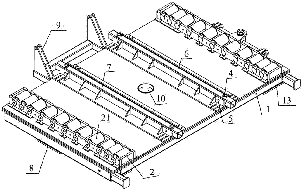
The invention discloses an overhaul and transport vehicle and method for a water-feeding pump motor. The overhaul and transport vehicle comprises a vehicle body (1) and universal wheels (2). The universal wheels (2) are arranged at the bottom of the vehicle body (1). The sliding wheel set (2) is fixedly arranged on the top of the vehicle body (1) and provided with a sliding plate which can slide on the sliding wheel set (2). The overhaul and transport method comprises the following steps: parking the overhaul and transport vehicle on one side of the water-feeding pump motor, making the surface of the overhaul and transport vehicle flush with the surface of the water-feeding pump motor mounting base, disassembling and ascending the water-feeding pump motor, arranging the sliding wheel set (2) and the sliding plate on the surface of the overhaul and transport vehicle and the surface of the water-feeding pump motor mounting base respectively, descending the water-feeding pump motor on the sliding plate, moving the water-feeding pump motor onto the overhaul and transport vehicle by enabling the sliding plate to slide, mounting and fixing, and finally transporting the water-feeding pump motor through the overhaul and transport vehicle and overhauling the water-feeding pump motor.

Description

technical field [0001] The invention relates to a transport trolley, in particular to an overhaul transport trolley for transporting a large feedwater pump motor, and a maintenance and transportation method for using the overhaul transport trolley to transport the feedwater pump motor out of a narrow factory building. Background technique [0002] Feed water pump motors are usually limited by the design of the plant and the narrowness of the maintenance site, making it difficult to carry out electric maintenance work normally. For example, after a motor failure, equipment repairs cannot be carried out immediately on the plant site. Especially after the motor is burned out, it is difficult to transport the motor weighing 40 to 50 tons out of the maintenance site by conventional methods, and it is also impossible to directly pump and wear the rotor at the installation position of the equipment (weighing more than ten tons and nearly three meters long). maintenance work, thus ...

Claims


Application Information

Patent Timeline
IPC IPC(8): B65G35/00
Inventor 裴玉龙张亚龙马志强郑义文
Owner CHINA SHENHUA ENERGY CO LTD
Learn More