Method for regulating and designing engine jet pipe throat area by taking installation performance into account

An engine nozzle and area adjustment technology, which is applied in the direction of machines/engines, calculations, jet propulsion devices, etc., can solve problems such as the difference in engine rear body resistance, limit the installation performance of the propulsion system, and achieve the effect of improving the installation thrust

Inactive Publication Date: 2015-01-21
中航空天发动机研究院有限公司
View PDF0 Cites 0 Cited by
  • Summary
  • Abstract
  • Description
  • Claims
  • Application Information

AI Technical Summary

Problems solved by technology

However, the throat area of ​​the nozzle has a great influence on the body resistance after flight. Therefore, when designing the engine throat area adjustment plan, only considering the non-installation thrust has limited the performance of the installation performance of the propulsion system.
At the same time, the adjustment plan form of nozzle throat area in the middle state of the existing engine is generally A 8 =f(T1), the throat area of ​​the nozzle is only related to the airflow temperature at the engine inlet, but through calculation and analysis, it is found that when the engine inlet temperature is the same, but the flight altitude and Mach number are different, the rear body resistance of the engine is different, so, Original A 8 =f(T1) The adjustment plan form no longer satisfies the nozzle throat area adjustment plan considering the installation performance, and a new engine nozzle throat area adjustment plan related to the engine flight height and Mach number needs to be designed

Method used


Image

  • Method for regulating and designing engine jet pipe throat area by taking installation performance into account
  • Method for regulating and designing engine jet pipe throat area by taking installation performance into account

Examples


Embodiment 1

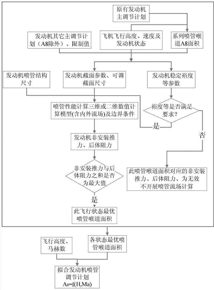
[0013] This embodiment provides a design method for adjusting the throat area of ​​the engine nozzle considering the installation performance, which is characterized in that: the design method for adjusting the throat area of ​​the engine nozzle considering the installation performance is as follows:

[0014] According to the flight altitude, Mach number and engine state, the engine main adjustment plan considering the non-installation performance is used to determine the nozzle throat area required by the engine at this time, and 70% of this area is taken as the minimum area, and 130% of this area % is taken as the maximum value, and is divided into a series of nozzle throat areas, which are divided into 10 equal parts; based on the engine master adjustment plan, engine limit value and series nozzle throat area, use engine zero-dimensional calculation software (such as turbotrans, etc.) Calculate the corresponding engine section parameters, adjustable section size, and engine ...


PUM


Abstract

The invention relates to a method for regulating and designing an engine jet pipe throat area by taking the installation performance into account. The method comprises the following steps of: determining a jet pipe throat area required by the engine at the moment according to a flight height, a mach number and an engine state by an original engine main regulating plan taking non-installation performance into account, and equally dividing the jet pipe throat area into a series of jet pipe throat areas by taking 70 percent of the area as a smallest area and 130 percent of the area as a maximum value; and calculating jet pipe flow fields under various throat areas by an engine main regulating plan, an engine limit value and the serial jet pipe throat areas, processing and calculating non-installation thrust and afterbody drag of the engine jet pipe, and selecting a maximum value of effective non-installation thrust and the afterbody drag, wherein a jet pipe throat area corresponding to the maximum value is an optimal jet pipe throat area in the state. The method has the advantages that on the premise of not changing the structure of the engine jet pipe and guaranteeing the stability margin of the engine, the regulating plan of the engine jet pipe throat area is needed to be modified only, and the engine installation thrust can be effectively improved.

Description

technical field [0001] The invention relates to the technical field of adjusting the throat area of ​​an engine nozzle, in particular to a design method for adjusting the throat area of ​​an engine nozzle considering installation performance. Background technique [0002] The existing aero-engine nozzle throat area adjustment plan is designed with full consideration of engine stability and component matching, and only considers the non-installation performance of the engine, but now advanced fighter jets require long-term operation without afterburner. Supersonic cruise, as the cruise speed increases, the flight resistance increases. The main components that analyze the resistance of the aircraft are: wings, fuselage, empennage, canopy and landing gear, etc. Among them, the resistance of the rear body of the fuselage accounts for 38-50% of the total aircraft resistance. However, the throat area of ​​the nozzle has a great influence on the body resistance after flight. There...

Claims


Application Information

Patent Timeline
Patent Type & Authority Patents(China)
IPC IPC(8): G06F17/50F02K1/11
Inventor 谢业平邱明星施磊赵肃芮长胜刘月玲
Owner 中航空天发动机研究院有限公司
Why Eureka
Try Eureka