
Method for determination of carbon dioxide emissions from steam generation systems

A generation system, carbon dioxide technology, applied in the direction of boiler working status indication, sustainable manufacturing/processing, climate sustainability, etc., can solve problems such as uncertainties

Inactive Publication Date: 2012-11-28
GENERAL ELECTRIC TECH GMBH
View PDF6 Cites 3 Cited by
  • Summary
  • Abstract
  • Description
  • Claims
  • Application Information

AI Technical Summary

Problems solved by technology

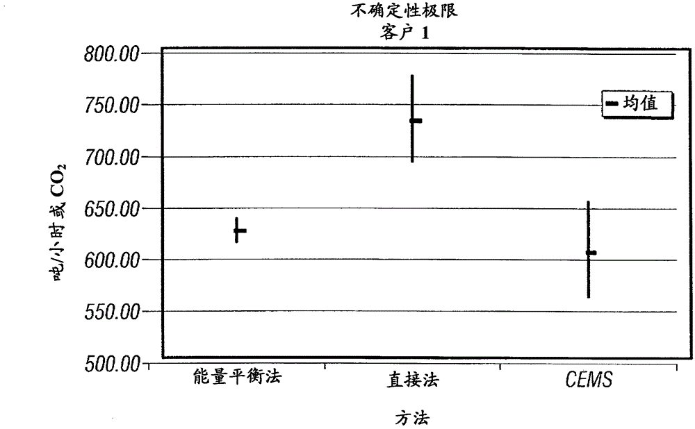
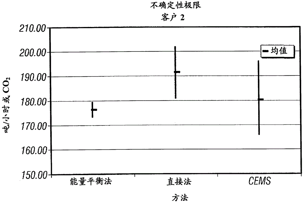
This large uncertainty becomes even more problematic when using the difference to determine changes in CO2 emissions

Method used


Image

  • Method for determination of carbon dioxide emissions from steam generation systems
  • Method for determination of carbon dioxide emissions from steam generation systems
  • Method for determination of carbon dioxide emissions from steam generation systems

Examples


Embodiment Construction

[0012] It will be understood that although the terms first, second, third, etc. may be used herein to describe various elements, components, regions, layers and / or sections, these elements, components, regions, layers and / or sections Should not be limited by these terms. These terms are only used to distinguish one element, component, region, layer or section from another element, component, region, layer or section. Thus, a first element, component, region, layer or section discussed below could be termed a second element, component, region, layer or section without departing from the teachings of the present invention. As used herein, the term "and / or" includes any and all combinations of one or more of the associated listed items.

[0013] The technical terms used herein are for the purpose of describing particular embodiments only and are not intended to be limiting. As used herein, the singular forms "a", "an" and "the" are intended to include the plural forms as well, ...


PUM


Abstract

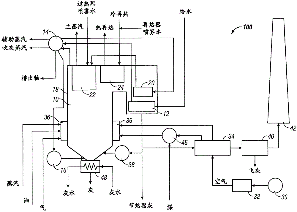
A method for determining carbon emissions from a steam generation system (100) is disclosed. It includes measuring a first energy of feedwater entering into a steam generation system (100) and measuring a second energy of steam exiting the steam generation system (100). The first energy is subtracted from the second energy to determine a total energy absorbed by the steam generation system (100). The total energy absorbed by the steam generation system (100) is divided by the total energy to determine a heat input to the steam generation system (100). The heat input is used to determine the carbon emissions from the steam generation system (100).

Description

[0001] Cross References to Related Applications [0002] This application claims priority to Provisional Application 61 / 184,136, filed June 4, 2009, and Provisional Application 61 / 244,278, filed September 21, 2009, the entire contents of which applications are incorporated herein by reference. technical field [0003] The present disclosure relates to a method for determining carbon dioxide emissions from a steam generation system used to heat a working fluid. Background technique [0004] As the world becomes increasingly concerned about emissions of greenhouse gases (and carbon dioxide in particular) there is a growing need to quantify these emissions as accurately as possible so that efforts can be directed towards reducing them. One way to reduce greenhouse gases is to improve existing technologies so that they become more efficient. However, even the best improvements to existing technologies lead to reductions in greenhouse gas emissions of around a few percent at be...

Claims


Application Information

Patent Timeline
IPC IPC(8): F22B37/38
CPCF22B37/38Y02P80/15
Inventor M·J·杜利
Owner GENERAL ELECTRIC TECH GMBH
Learn More