Heat pump hydronic heater

A hot water heating, heat pump technology, applied in hot water central heating systems, heating methods, household heating and other directions, can solve problems such as difficulty in warming

Inactive Publication Date: 2012-12-05
PANASONIC CORP
View PDF10 Cites 6 Cited by
  • Summary
  • Abstract
  • Description
  • Claims
  • Application Information

AI Technical Summary

Problems solved by technology

[0003] However, in conventional air conditioners, there are problems such as difficulty in warming the feet during heating, and in order to solve these problems, a hot water heater using heat pump technology has been developed (Patent Document 1)

Method used


Image

  • Heat pump hydronic heater
  • Heat pump hydronic heater
  • Heat pump hydronic heater

Examples


Embodiment Construction

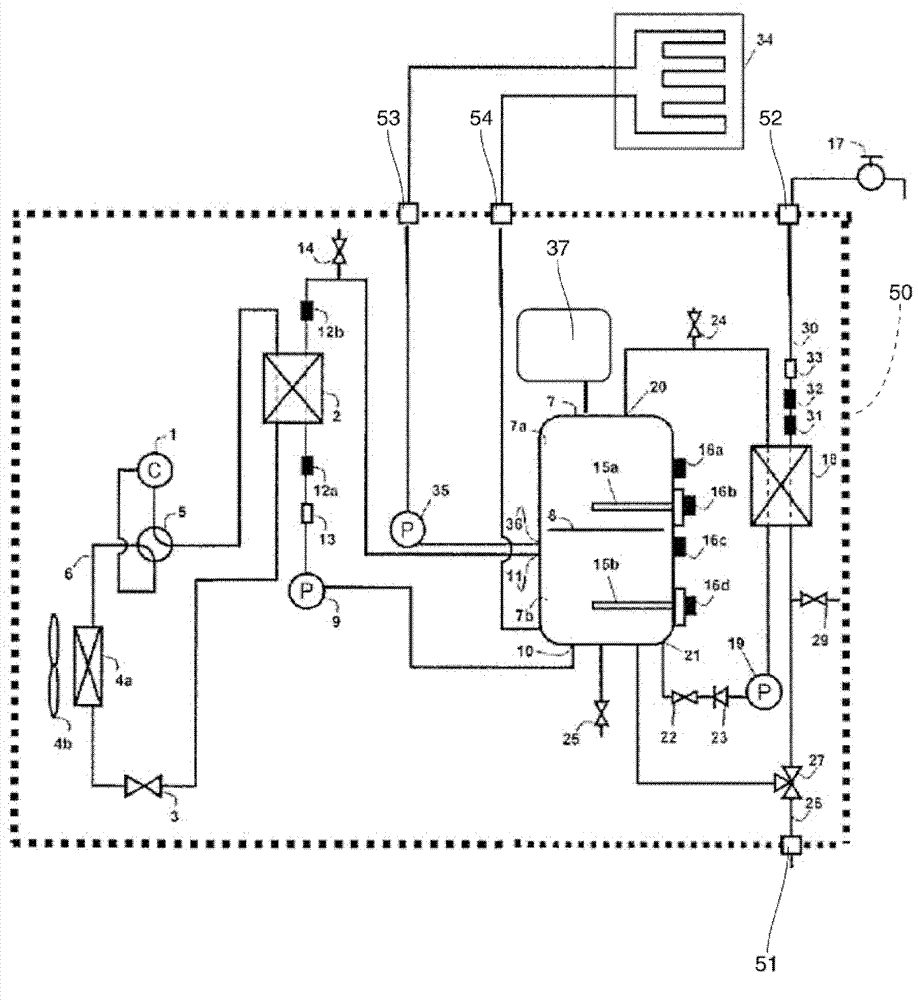
[0072] In the heat pump hot water heating device of the first invention, the hot water storage tank is connected with the closed expansion tank. According to the present invention, it is possible to absorb the expansion of water in the circulation path constituting the hot water storage tank circuit.

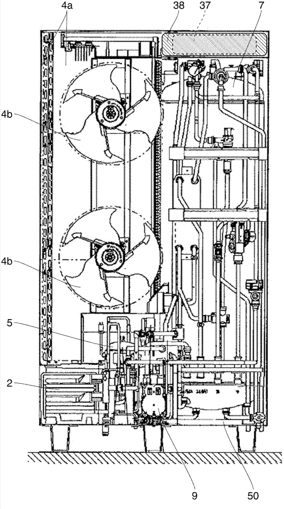
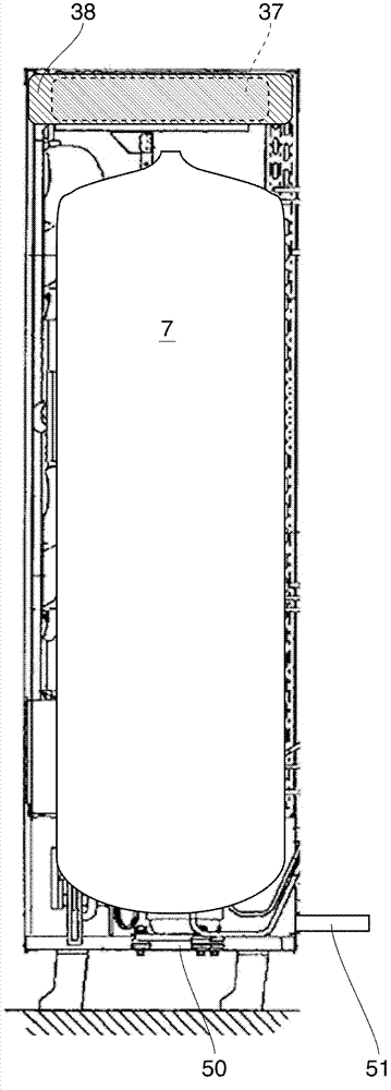
[0073] In the heat pump type hot water heating device of the second invention, especially in the first invention, a vertically long cylindrical tank is used as the hot water storage tank, and a blower fan for blowing air to the evaporator is installed, and the hot water storage tank The evaporator and the blower fan are arranged in the other space in the width direction of the frame, and the expansion tank is arranged at a position higher than the hot water storage tank. According to the present invention, the heat pump circuit and the hot water storage tank circuit can be accommodated in the frame, and by locating the expansion tank at a higher position than the hot water stora...


PUM


Abstract

Provided is a hat pump hydronic heater in which the heat pump circuit and the hot water tank circuit can be accommodated in one casing, and it is possible to absorb expansion of water in the circulation path when hot water in the hot water tank is circulated through heat a floor or supply hot water. The heat pump hydronic heater of the invention includes a heat pump circuit and a hot water tank circuit, the heat pump circuit and the hot water tank circuit are accommodated in one casing (50).

Description

technical field [0001] The present invention relates to a heat pump type hot water heater for heating with hot water generated using a heat pump circuit. Background technique [0002] In the prior art, the use of heating equipment using combustion fuels such as oil and gas as a heat source accounts for most of the utilization, but in recent years, the heating market using heat pump technology has expanded rapidly. Moreover, some of the existing air conditioners utilize heat pump technology so as to be able to utilize both cooling and heating. [0003] However, conventional air conditioners have problems such as difficulty in warming the feet during heating. To solve these problems, a hot water heater utilizing heat pump technology has been developed (Patent Document 1). [0004] In the hot water heater described in Patent Document 1, high-temperature refrigerant and water are subjected to heat exchange, and hot water heated by the heat exchange is sent to a heating terminal...

Claims


Application Information

Patent Timeline
Patent Type & Authority Applications(China)
IPC IPC(8): F24D3/18
CPCF24H4/04F24H9/02F24H9/06
Inventor 福永敏克青山繁男谏山安彦
Owner PANASONIC CORP
Why Eureka
Try Eureka