Device for drawing wall surface curves and ceiling curves and use method thereof

A curve and ceiling technology, applied in the field of custom furniture, can solve the problems of long drawing time and low precision, and achieve the effect of shortening drawing time, improving work efficiency and improving drawing accuracy

Active Publication Date: 2012-12-12
SUOFEIYA HOME COLLECTION
View PDF6 Cites 3 Cited by
  • Summary
  • Abstract
  • Description
  • Claims
  • Application Information

AI Technical Summary

Problems solved by technology

[0006] The purpose of the present invention is to propose a device and method for drawing wall curves and ceiling curves, which can solve the problems of long drawing time and low precision in the prior art

Method used


Image

  • Device for drawing wall surface curves and ceiling curves and use method thereof
  • Device for drawing wall surface curves and ceiling curves and use method thereof
  • Device for drawing wall surface curves and ceiling curves and use method thereof

Examples


Embodiment 1

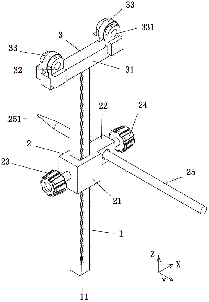
[0039] Such as figure 1 As shown, the device for drawing wall curves and ceiling curves includes a cylinder 1 , a brush fixing mechanism 2 and a rolling mechanism 3 .

[0040] The brush fixing mechanism 2 includes a sleeve body 21 with a first through hole (not shown in the figure), a brush fixing body 22 with a second through hole (not shown in the figure), a paintbrush 25, a first hand Tighten the screw 23 and a second finger screw 24, the sleeve body 21 is socketed with the cylinder body 1 through the first middle through hole, the paintbrush fixed body 22 is fixed on one side of the sleeve body 21, and the paintbrush fixed body 22 passes through the second middle through hole. The hole is socketed with the paintbrush 25; the first thumb screw 23 is screwed to the other side of the sleeve body 21, and the end of the first thumb screw 23 is in contact with the cylinder 1, and the first thumb screw 23 is used to screw the sleeve The body 21 is locked on the cylinder 1, so th...

Embodiment 2

[0052] combine figure 1 , The difference between this embodiment and Embodiment 1 lies in the structure of the board clip. Specifically, such as Figure 9 As shown, the plate clamp 5 includes a connecting rod 51 , a clamping portion 52 and a placing portion 53 , the clamping portion 52 is fixed on the top of the connecting rod 51 , and the placing portion 53 is fixed on the bottom of the connecting rod 51 .

[0053] The usage method of this embodiment is basically the same as that of Embodiment 1, except that the installation method of the board clamp 5 is different. When used, such as Figure 10 As shown, the clamping part 52 is clamped on the top line reinforcement bar 501 of the cabinet body 500, and the bottom of a plate is placed on the placement part 53; the roller 33 of the rolling mechanism 3 is in contact with the ceiling, and the paintbrush 25 of the brush fixing mechanism 2 The nib 251 is in contact with the surface of the board.

Embodiment 3

[0055] This example directly uses figure 1 The device shown, without accessories. Such as Figure 11 As shown, directly place the bottom of a rectangular or square plate 800 on the ground, then make the roller 33 of the rolling mechanism 3 contact the wall 700, and make the nib 251 of the paintbrush 25 of the brush fixing mechanism 2 touch the plate Push the cylinder 1, and keep the roller 33 of the rolling mechanism 3 in contact with the wall 700, the nib 251 of the paintbrush 25 slides along the surface of the plate 800 and leaves a curve 900; saw along the curve 900 Open the panel 800, and install the fabricated panel 800 on the cabinet body 600 so that it is closed with the wall 700.


PUM


Abstract

The invention relates to a device for drawing wall surface curves and ceiling curves and a use method thereof. The device comprises a pillar, a painting brush fixing mechanism and a rolling mechanism, wherein the painting brush fixing mechanism comprises a sleeve body provided with a first middle through hole, a painting brush fixing body provided with a second middle through hole, a painting brush, a first manually turning screw and a second manually turning screw, the sleeve body is in cup joint with the pillar through the first middle through hole, the painting brush fixing body is fixed at one side of the sleeve body, the painting brush fixing body is in cup joint with the painting brush through the second middle through hole, the first manually turning screw is connected with the other side of the sleeve body through threads, the end part of the first manually turning screw is contacted with the pillar, the second manually turning screw is connected with one side of the painting brush fixing body through threads, and the end part of the second manually turning screw is contacted with the painting brush; and the rolling mechanism comprises a roller support part and at least two rollers, the roller support part is fixedly arranged on the top of the pillar, and the rollers are arranged on the top of the roller support part and can rotate freely. According to the device for drawing the wall surface curves and the ceiling curves and the use method thereof disclosed by the invention, the drawing time can be greatly shortened, the drawing precision can be improved, and the working efficiency is improved.

Description

[0001] technical field [0002] The invention relates to customized furniture technology, in particular to a device for drawing wall curves and ceiling curves and a method for using the same. [0003] Background technique [0004] With the rapid development of the economy, more and more people like to customize and make personalized furniture according to the shape of their interior space. The furniture made according to the shape of the indoor space is more in line with the requirements of space utilization, and can also form a seamless connection with the wall or ceiling. However, for some curved walls or ceilings, it often takes a lot of time to measure when making the sealing plate, so that the shape of the sealing plate can be made to match the curved wall or ceiling. The current practice is to use different measuring tools (such as rulers, gauges, etc.) to measure the arc and path of the wall or ceiling, which takes a long time to draw and has low accuracy. [0005]...

Claims


Application Information

Patent Timeline
Patent Type & Authority Applications(China)
IPC IPC(8): B25H7/04
Inventor 张李飞
Owner SUOFEIYA HOME COLLECTION
Why Eureka
Try Eureka