Fluid distributor

A fluid distribution device and fluid technology, applied in lighting and heating equipment, heat exchange equipment, heat exchanger shells, etc., can solve problems such as uneven flow distribution

Active Publication Date: 2012-12-12
SUZHOU BSE AIR CONDITIONER
View PDF5 Cites 4 Cited by
  • Summary
  • Abstract
  • Description
  • Claims
  • Application Information

AI Technical Summary

Problems solved by technology

[0005] Therefore, the technical problem to be solved by the present invention is to overcome the problem of uneven flow distribution of fluid distribution devices in the prior art, thereby providing a fluid distribution device with uniform fluid flow distribution

Method used


Image

  • Fluid distributor
  • Fluid distributor
  • Fluid distributor

Examples


Embodiment 1

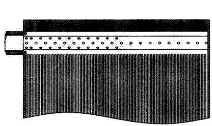
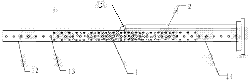
[0024] Such as figure 2 As shown, this embodiment provides a fluid distribution device, including a distribution pipeline 1, both ends of which are closed, and a plurality of through holes 13 communicating with the branches are arranged on the side wall, for distributing fluid to each branch; The pipeline 2 communicates with the distribution pipeline 1 through a joint 3 arranged in the upper middle of the distribution pipeline 1, and is used for distributing fluid to both sides of the distribution pipeline 1; the distribution pipeline 1 and The supply pipelines 2 are arranged side by side in parallel, and the joint 3 divides the distribution pipeline 1 into a first part 11 and a second part 12 which communicate with each other. The density of the plurality of through holes 13 gradually decreases from the joint 3 to both ends, the joint 3 forms an acute angle with the first part 11, and forms an obtuse angle with the second part 12, in order to Ensure that the sum of the cros...

Embodiment 2

[0029] This embodiment provides a fluid distribution device, including a distribution pipeline 1, both ends of which are closed, and a plurality of through holes 13 communicating with the branches are arranged on the side wall for distributing fluid to each branch; the flow supply pipeline 2 , communicating with the distribution pipeline 1 through the joint 3 arranged in the upper middle position of the distribution pipeline 1, for distributing fluid to both sides of the distribution pipeline 1; the distribution pipeline 1 and the supply The flow pipelines 2 are arranged side by side in parallel, and the joint 3 divides the distribution pipeline 1 into a first part 11 and a second part 12 that communicate with each other. The density of the through holes 13 gradually decreases from the joint 3 to both ends, the joint 3 forms an acute angle with the first part 11, and forms an obtuse angle with the second part 12. The sum of the cross-sectional areas of the several through hole...


PUM


Abstract

The invention provides a fluid distributor comprising a distribution pipe and a fluid supply pipe, wherein two ends of the distribution pipe are closed, the side wall of the distribution pipe is provided with a plurality of through holes which are communicated with branches and used for distributing fluid to each branch; the fluid supply pipe is communicated with the distribution pipe through a connector arranged at the middle position of the upper part of the distribution pipe and used for distributing fluid to two sides of the distribution pipe; the distribution pipe and the fluid supply pipe are arranged in parallel, the connector divides the distribution pipe into a first part and a second part which are mutually communicated, and the density of a plurality of through holes positioned in the first part and the second part is gradually reduced from the connector towards two ends; the connector forms an acute included angle with the first part and forms an obtuse included angle with the second part; and the sum of the sectional areas of the plurality of through holes in a certain region of the first part is smaller than the sum of the sectional areas of a plurality of through holes in the symmetrical region of the second part. The fluid distributor provided by the invention can guarantee the uniform distribution of fluid flow.

Description

technical field [0001] The invention relates to a fluid distribution device, which belongs to the field of fluid distribution. Background technique [0002] When the fluid flows in the pipeline, it usually needs to distribute the flow according to the demand, and the unbalanced flow distribution will often make the system unstable. In the plate heat exchanger of the air conditioning system, because the plate heat exchanger is larger and thicker, the flow velocity of the fluid when it first enters the plate heat exchanger is relatively large, and it passes through the interface part quickly, resulting in less fluid flow distributed by the inlet part. Most of the fluid accumulates inside the plate heat exchanger, making the flow into each plate unbalanced, resulting in insufficient heat exchange. [0003] In order to solve the above problem of uneven flow distribution, Chinese patent document CN101008560A discloses a fluid distribution device, such as figure 1 As shown, its ...

Claims


Application Information

Patent Timeline
Patent Type & Authority Applications(China)
IPC IPC(8): F28F9/22
Inventor 查晓冬
Owner SUZHOU BSE AIR CONDITIONER
Why Eureka
Try Eureka