Injection pressurizing structure of die-casting machine

A pressurized structure and die-casting machine technology, which is applied in the field of die-casting machines, can solve the problems of poor sealing effect of the conical Bell line, unstable pressure-holding effect, slow boosting speed, etc., to achieve stable pressure-holding effect, not easy to leak, The effect of supercharging speed

Inactive Publication Date: 2014-05-21
汪俊成
View PDF6 Cites 0 Cited by
  • Summary
  • Abstract
  • Description
  • Claims
  • Application Information

AI Technical Summary

Problems solved by technology

[0003] What the present invention aims to solve is that the installation and machining accuracy of the floating piston and the floating spool in the traditional floating piston pressurization are relatively high. Slow, long time to build pressure, and unstable pressure holding effect

Method used


Image

  • Injection pressurizing structure of die-casting machine

Examples


Embodiment Construction

[0010] In order to make the technical means, creative features, goals and effects achieved by the present invention easy to understand, the present invention will be further described below in conjunction with specific illustrations.

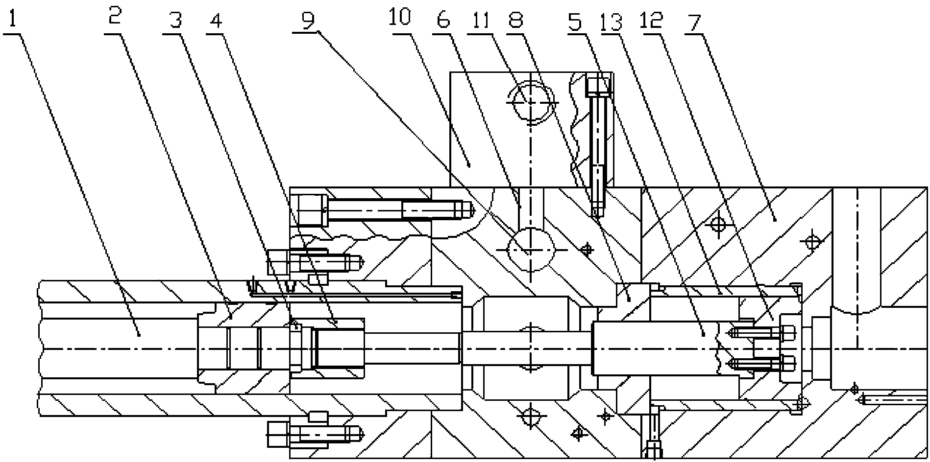
[0011] Such as figure 1 As shown, the injection booster structure of the die-casting machine includes the injection piston rod 1, the injection piston 2 arranged on the injection piston rod 1, and the split card arranged on the injection piston rod 1 outside the injection piston 2 Ring 3, the booster piston rod 5 connected with the injection piston rod 1 through the nut 4, the injection valve plate 6 and the booster valve plate 7 arranged outside the booster piston rod 5, the booster valve plate 7 and the injection valve There is a pressurized guide sleeve 8 on the pressurized piston rod between the plates 6, and an injection oil passage 9 is provided on the injection valve plate 6. The injection pressurized structure of the die-casting machine ...


PUM


Abstract

The invention provides an injection pressurizing structure of a die-casting machine, comprising an injection piston rod, an injection piston, a card opening ring, a nut, a pressurizing piston rod, an injection valve plate, a pressurizing valve plate and a guide sleeve, wherein the injection valve plate is provided with an injection oil path. The injection pressurizing structure is characterized in that the injection pressurizing structure of the die-casting machine further comprises a rapid injection valve plate arranged on the injection valve plate; the rapid injection valve plate is provided with a rapid injection oil path; the injection valve plate and the rapid injection valve plate are provided with a two-way plugging-in valve; the two-way cartridge valve comprises a two-way plugging-in throttling valve and a hydraulic control one-way valve; the two-way plugging-in throttling valve is connected with a rapid injection oil path through an oil pipe; and the hydraulic control one-way valve is connected with an injection oil path through an oil pipe. The injection pressurizing structure of the die-casting machine has the advantages of fast pressurizing speed, short pressure establishing time, good sealing effect and uneasiness of being leaked, and enables an injection system to have a more stable pressure-keeping effect.

Description

Technical field: [0001] The invention relates to the technical field of die-casting machines, in particular to an injection pressurized structure of a die-casting machine. Background technique: [0002] The injection system of the die-casting machine is a key component that determines the product performance of the die-casting machine. At present, the traditional die-casting machine basically adopts a double-circuit three-stage injection system that uses a floating piston to boost pressure. The installation and machining accuracy of the floating piston and the floating spool in this injection and booster structure require high precision. If the installation of the floating piston and the floating spool are not on the same axis, the sealing effect of the Bell line on the cone surface of the floating piston and the floating spool will Not good, it is easy to leak, resulting in unstable pressure holding. The supercharging piston pushes the floating spool to seal with the bell ...

Claims


Application Information

Patent Timeline
Patent Type & Authority Patents(China)
IPC IPC(8): B22D17/20
Inventor 汪俊成
Owner 汪俊成
Why Eureka
Try Eureka