
Powered below-knee prosthesis

A power and prosthetic technology, applied in the fields of prosthesis, medical science, artificial legs, etc., can solve the problems of unnatural walking speed, stiffness of the forefoot and heel, and easy fatigue of amputees, so as to meet the needs of deformation and good energy storage. and shock absorption, light weight effect

Active Publication Date: 2013-01-16
北京工道风行智能技术有限公司
View PDF8 Cites 4 Cited by
  • Summary
  • Abstract
  • Description
  • Claims
  • Application Information

AI Technical Summary

Problems solved by technology

[0002] Below-the-knee prostheses currently in use are mainly divided into passive prostheses and active prostheses. The ankle joints of passive prostheses use single-axis ankles or universal ankle joints. The existing problem is that the walking speed cannot follow the amputee's walking speed naturally and freely. And changes, patients are often forced to lean forward to make up for the lack of propulsion ability, making amputee more likely to feel fatigue; active prosthetics are driven by motors, which can provide enough energy for the body to move forward, so as to realize the natural gait of the human body, but At present, the design of active prosthetics on the ankle joint is relatively simple, which cannot meet the needs of users well.
In addition, most of the prosthetic feet currently used for below-knee prosthetics are made of wood or plastic. Due to the limitations of their own materials, the forefoot and heel of the prosthetic foot are relatively stiff, which cannot meet the deformation requirements of normal gait and affect the walking ability of the user. Patients' demand for bionic functions of prosthetic products

Method used


Image

  • Powered below-knee prosthesis
  • Powered below-knee prosthesis

Examples


Embodiment Construction

[0013] The present invention will be described in detail below in conjunction with the accompanying drawings and embodiments.

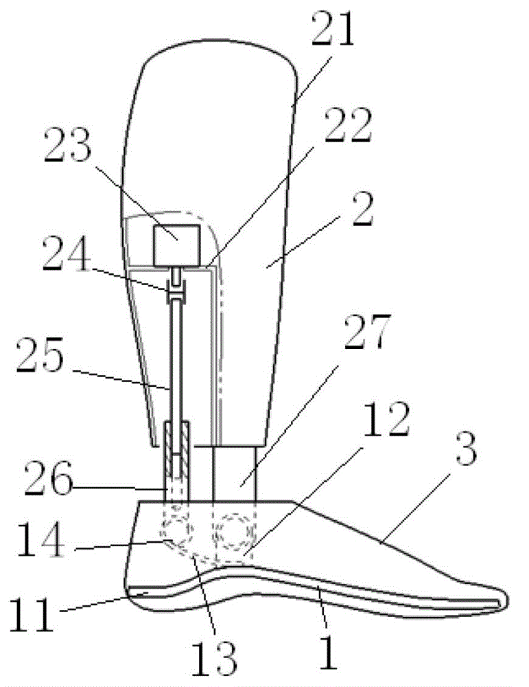
[0014] like figure 1 As shown, the present invention includes a prosthetic foot 1 and a calf prosthesis 2, and may also include a foot cover 3 wrapped outside the prosthetic foot 1.

[0015] The prosthetic foot plate 1 of the present invention comprises a foot plate 11, the middle part of the foot plate 11 has a higher arch, and a seat 12 is fixedly arranged on the top surface of the foot plate 11 at the arched part. The rear portion of the foot plate 11 is provided with an upwardly curved elastic connecting rod 13, the front portion of the elastic connecting rod 13 is fixedly connected to the top of the arched part of the foot plate 11, and an elastic movable space is arranged between the rear portion of the elastic connecting rod 13 and the foot plate 11. And another support 14 is fixedly arranged on the top of the rear end of the elastic connectin...


PUM


Abstract

The invention relates to a powered below-knee prosthesis which is characterized by comprising a prosthesis foot and a prosthesis shank. The prosthesis foot is made of carbon fiber boards. An upward arch is arranged in the middle of the prosthesis foot. A support is fixed to the top surface of the arch. An elastic connecting rod bending upwards is disposed at the rear of the prosthesis foot. The front of the elastic connecting rod is fixedly connected to the top of the arch. An elastic moving space is arranged between the rear of the elastic connecting rod and the prosthesis foot. Another support is disposed on the top surface of the rear of the elastic connecting rod. The prosthesis shank comprises a shell which simulates the shape of a human shank. A motor is fixed in the shell. An output end of the motor is connected with a screw. The screw is connected with a screw sleeve in a threaded manner. The bottom end of the screw sleeve penetrates out of the shell and is connected to the support on the top surface of the elastic connecting rod. A support column is disposed at the bottom, in front of the screw sleeve, of the shell. The bottom end of the support column is hinged to the support on the top surface of the arch. The powered below-knee prosthesis is widely applicable to various amputation patients.

Description

technical field [0001] The invention relates to a human prosthesis, in particular to a dynamic under-knee prosthesis combining active and passive movement modes. Background technique [0002] Below-the-knee prostheses currently in use are mainly divided into passive prostheses and active prostheses. The ankle joints of passive prostheses use single-axis ankles or universal ankle joints. The existing problem is that the walking speed cannot follow the amputee's walking speed naturally and freely. And changes, patients are often forced to lean forward to make up for the lack of propulsion ability, making amputee more likely to feel fatigue; active prosthetics are driven by motors, which can provide enough energy for the body to move forward, so as to realize the natural gait of the human body, but At present, the design of active prostheses about the ankle joint is relatively simple, which cannot well meet the needs of users. In addition, most of the prosthetic feet currently...

Claims


Application Information

Patent Timeline
Patent Type & Authority Applications(China)
IPC IPC(8): A61F2/60A61L27/18
Inventor 王平立曾一民苑广辉王启宁
Owner 北京工道风行智能技术有限公司
Learn More