
Flexible powered below-knee prosthesis
A dynamic and flexible technology, applied in the field of below-knee prosthetics, can solve the problems of unnatural walking speed, stiff forefoot and heel, and easy fatigue of amputees, so as to meet the needs of deformation, good energy storage and shock absorption, and light weight Effect
- Summary
- Abstract
- Description
- Claims
- Application Information
AI Technical Summary
Problems solved by technology
Method used
Image

Examples
Embodiment 1
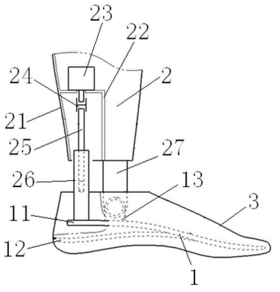
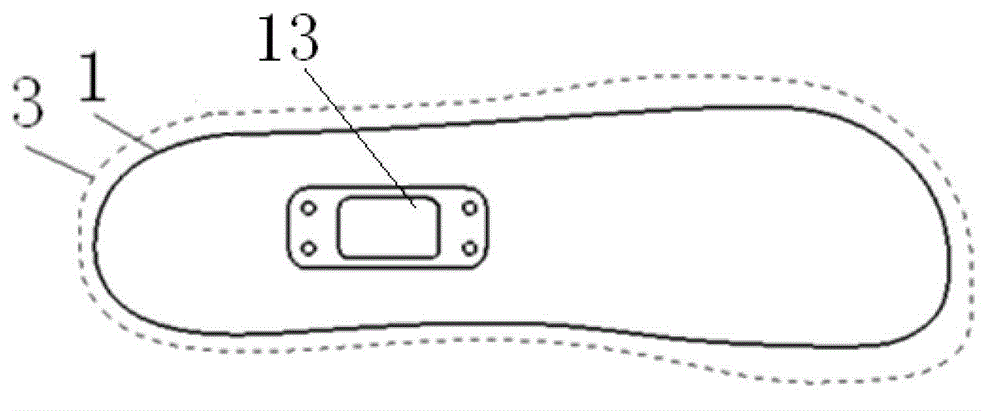
[0018] Such as figure 1 , figure 2 As shown, the present invention includes a prosthetic foot 1 and a calf prosthesis 2, and may also include a foot cover 3 wrapped outside the prosthetic foot 1.
[0019] The prosthetic foot plate 1 of the present invention comprises an upper foot plate 11 and a heel elastic piece 12, the front portion of the heel elastic piece 12 is fixedly connected to the middle part of the bottom surface of the upper foot plate 11, and there is an elastic movable space between the rear portion of the heel elastic piece 12 and the upper foot plate 11 , The top surface of the upper foot plate 21 rear portion is provided with a seat 13 .
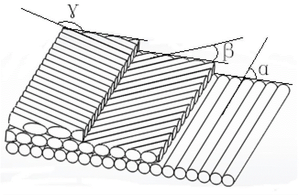
[0020] Such as image 3 As shown, the foot plate 11 and the heel shrapnel 12 are both made of carbon fiber boards. The carbon fiber boards are made of carbon fiber cloth through the lay-up design of the prior art. The thickness of each section of the carbon fiber board is uniform and the surface is smooth. However, the ...
Embodiment 2
[0023] Such as Figure 4 As shown, this embodiment is basically the same as Embodiment 1, and its difference from Embodiment 1 is that not only a support 13 is provided on the top of the upper foot plate 11, but another support 14 is also provided behind the support 13. . When the bottom end of the screw sleeve 26 passes through the housing 21, it is not fixedly connected to the top of the upper foot plate 11, but hinged on the support 14. This can make the movement between the prosthetic foot plate 1 and the calf prosthesis 2 more flexible.
[0024] In the above two embodiments, if figure 2 As shown, a foot cover 3 corresponding to the shape of the human foot can be arranged on the outside of the prosthetic foot plate 1. The foot cover 3 can be made of polyurethane material, which has properties such as corrosion resistance, wear resistance and electrical insulation.
[0025] In the above embodiments, the motor 23 has an independent power supply device, and the output sha...
PUM
 Abstract
Description
Claims
Application Information