Structure and method for replacing water beam and stand column of heating furnace

A heating furnace and water beam technology, applied to heat treatment furnaces, furnaces, furnace types, etc., can solve the problems of waste of resources, increase economic investment, increase labor, and achieve high efficiency

Active Publication Date: 2013-01-23
CHINA 19TH METALLURGICAL CORP
View PDF1 Cites 11 Cited by
  • Summary
  • Abstract
  • Description
  • Claims
  • Application Information

AI Technical Summary

Problems solved by technology

[0003] When the water beams and columns inside the walking or pushing steel heating furnace need to be completely replaced during maintenance, there is only one method before the construction unit and the owner, that is to replace all the roof steel structures on the top of the heating furnace All dismantling is similar to the principle of opening the top of a sealed volume, and then relying on the driving in the factory to replace all the water beams and columns. This traditional construction technology has brought adverse consequences, mainly focusing on The following three aspects: 1. Heavy reliance on the crane in the factory building as a hoisting tool, which leads to the removal of all equipment on the furnace roof when repairing and replacing the water beam and column, that is, "opening the cover" to remove the water beam and column by driving and installation; 2. Remove and install the water beams and columns after removing all equipment on the furnace top, which not only increases the construction period, but also increases the amount of maintenance work; 3. Increases economic investment. After "opening the cover", it needs to be reinstalled Ordering and replacing the structure and accessories of the furnace top equipment has caused a waste of resources; at the same time, it will inevitably increase the amount of labor

Method used


Image

  • Structure and method for replacing water beam and stand column of heating furnace
  • Structure and method for replacing water beam and stand column of heating furnace
  • Structure and method for replacing water beam and stand column of heating furnace

Examples


Embodiment Construction

[0027] The present invention will be further described below in conjunction with accompanying drawing.

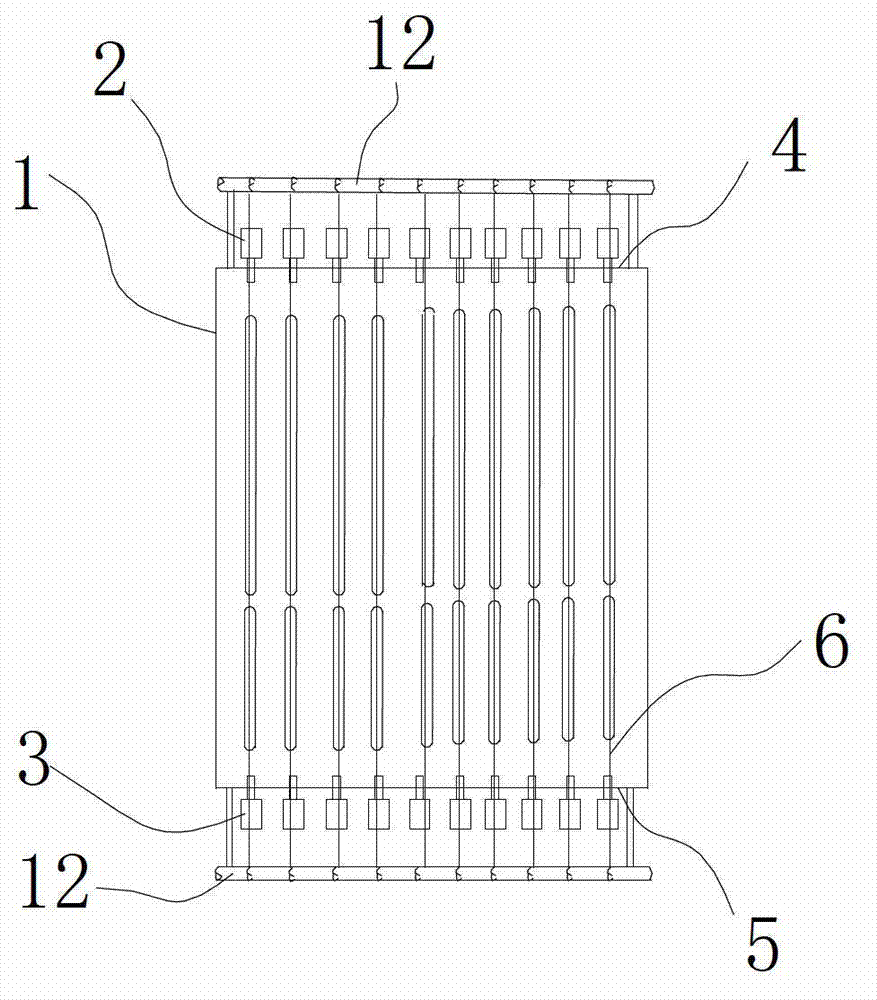
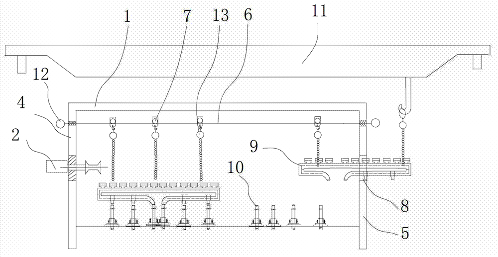
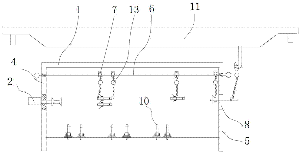
[0028] Such as Figure 1 to Figure 5 As shown, the present invention comprises a furnace body 1, a furnace-in cantilever roll 2 and a furnace-out cantilever roll 3, and the furnace-in cantilever roll 2 and the furnace-out cantilever roll 3 are respectively arranged on the left side wall 4 and the right side wall 5 of the furnace body 1 , the furnace-in cantilever rollers 2 are arranged in a row at the same level on the left side wall 4, and the furnace-in cantilever rollers 3 are arranged in a row at the same level on the right side wall 5, and the furnace-in cantilever rollers 2 It is located on the same level as the furnace cantilever roller 3 and corresponds one by one, and also includes a cable 6, a pulley 7 and a lifting device 13; the left side wall 4 is provided with a row of left fixing holes, and the left fixing hole is connected with the furnace inlet cantilever r...


PUM


Abstract

The invention discloses a maintenance replacement structure, and particularly relates to a replacement structure of a water beam and a stand column of a heating furnace, which is capable of avoiding damage to the top of the furnace. When the water beam and the stand column are replaced, a mooring rope ropeway is established on the basis of a lateral wall, then, the water beam and the stand column are send out from a beam and column outlet by virtue of a hoisting device and a pulley, and a new water beam and a new stand column are fed from the beam and column outlet by virtue of the hoisting device and the pulley. Therefore, a crane is not needed to hoist the water beam and the stand column, and the steel structure at the top of the furnace does not need to be dismantled. A mooring rope is accurately positioned by a furnace feeding suspension roller and a furnace discharging suspension roller, and simultaneously, the hoisting distance is short, therefore, the water beam and the stand column can be sent into or sent out of the heating furnace in a quicker, more accurate and more efficient way than other manners in overhauling. Since the position of the mooring rope is fixed, a path for hoisting and sending the water beam and the stand column is also fixed, thereby avoiding accidents caused by collision of the water beam and the stand column with other objects.

Description

technical field [0001] The invention relates to a maintenance and replacement structure, in particular to a replacement structure for water beams and columns of a heating furnace. In addition, the present invention also relates to a method for maintenance and replacement, especially a method for replacing water beams and columns of a heating furnace. Background technique [0002] The water beams and columns of the walking and pushing steel heating furnaces are arranged inside the heating furnace, surrounded by steel structures and masonry refractories around the furnace and the furnace roof, and the water beams and columns are mainly used for connecting Hold the steel billet coming in from the entrance of the heating furnace, and then the billet is supported by the water beam and column and is continuously heated in the heating furnace, and finally the heated billet is sent to the exit of the heating furnace through the water beam and column and sent to the rolling line for ...

Claims


Application Information

Patent Timeline
Patent Type & Authority Applications(China)
IPC IPC(8): C21D9/70
Inventor 田渡彬余伟杨文辉张华文解云程仕亿刘玉海龚元明张令王建军肖建谭为刘显勇
Owner CHINA 19TH METALLURGICAL CORP
Why Eureka
Try Eureka