Method for attaching a trim to a clock casing element and casing element manufactured according to said method

A technology for external components and clocks, applied to clocks, mechanically driven clocks, visually indicating time, etc., can solve problems such as hole clogging, holes not having clean edges, etc.

Active Publication Date: 2013-01-23
THE SWATCH GRP RES & DEVELONMENT LTD
View PDF6 Cites 7 Cited by
  • Summary
  • Abstract
  • Description
  • Claims
  • Application Information

AI Technical Summary

Problems solved by technology

[0003] If electrodeposition is done after this operation, the holes will be clogged with deposits and another hole machining operation will be required, so the deposits

Method used


Image

  • Method for attaching a trim to a clock casing element and casing element manufactured according to said method
  • Method for attaching a trim to a clock casing element and casing element manufactured according to said method
  • Method for attaching a trim to a clock casing element and casing element manufactured according to said method

Examples


Embodiment Construction

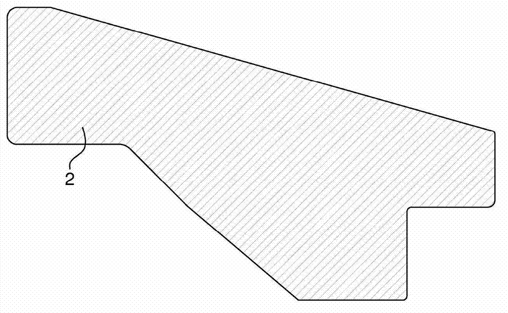
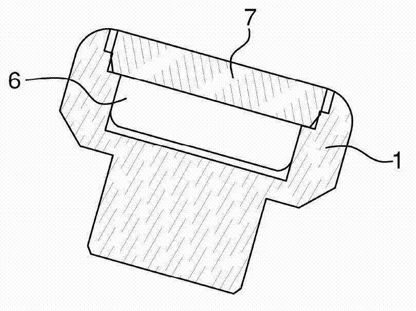
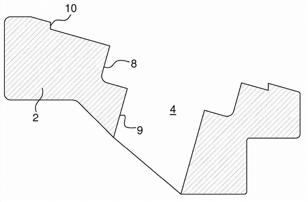
[0015] figure 1 The timepiece exterior element 2 is shown, which is called "base", into which the decoration will be integrated. More specifically, the element here is the bezel. figure 2 Decoration 1 is shown. It is a phosphor plate 6 arranged under the sapphire glass 7 carried by the decoration 1 . The phosphorescent sheet is called "luminova" (registered trademark). exist image 3 , substrate 2 is perforated on both sides. According to a variant, said holes may be blind holes. The perforations include a plurality of steps or shoulders. The stepped portions 8 and 9 are used to receive the phosphor sheet 1, and the stepped portion 10 is used to receive electrodeposits which will be described below.

[0016] Such as Figure 4 As shown, the mold part 5 is inserted into the perforated base 2 . The model parts are temporary inserts forming an essential part of the invention. It prevents later electrodeposition from penetrating into the holes 8, therefore, the mold part...


PUM


Abstract

Method for securing a decoration (1) to an external timepiece element (2) coated with a galvanically deposited metallic layer (3). Instead of the decoration (1), a dummy part (5) is temporarily placed in the hole (4) pierced in the external element (2), and the galvanic deposition (3) is then carried out. After the deposition has been levelled, the dummy part (5) is removed and the decoration is placed in the hole (4).

Description

technical field [0001] The invention relates to a method for fixing a decoration or an insert to a timepiece exterior element, which is coated with an electrodeposited metal layer, and to an exterior element manufactured according to this method. Background technique [0002] When a decoration is inserted or integrated in a timepiece exterior element and this element has to be coated with an electrodeposited metal layer, the element is first at least partially perforated, the holes thus formed matching the dimensions of the decoration to be integrated. [0003] If electrodeposition is done after this operation, the holes will be clogged with deposits and another hole machining operation will be required, so the deposits around the entrance of the holes will be at risk of being scratched and the holes will not have clean edges , which is aesthetically unacceptable for high-end timepieces. Contents of the invention [0004] Therefore, in addition to complying with the state...

Claims


Application Information

Patent Timeline
IPC IPC(8): G04B47/04
CPCG04B19/12G04B45/0076G04B19/283G04B19/103G04B47/042A44C17/04G04B19/286Y10T156/1056Y10T29/49826
Inventor P·格罗森巴赫T·弗勒利歇尔
Owner THE SWATCH GRP RES & DEVELONMENT LTD
Why Eureka
Try Eureka