Shielded connector

A technology of connectors and shielding shells, which is applied in the field of shielding connectors, and can solve problems such as reducing the accuracy of clamping and vibration of the inner shell

Inactive Publication Date: 2013-01-23
YAZAKI CORP
View PDF7 Cites 16 Cited by
  • Summary
  • Abstract
  • Description
  • Claims
  • Application Information

AI Technical Summary

Problems solved by technology

[0007] However, if the inner case is smaller than the extent of the shield shell to both side plates of the shield case cover, the inner case may Vibration is generated inside the shielded case
If vibration of the inner case occurs during the crimping operation, it may reduce the accuracy of the crimping

Method used


Image

  • Shielded connector
  • Shielded connector
  • Shielded connector

Examples


Embodiment Construction

[0030] Next, a shielded connector according to an embodiment of the present invention will be described with reference to the drawings.

[0031] The shielded connector 11 according to the present embodiment can be preferably used as a shielded connector on the cable side of USB 2.0 (differential connector for high-speed transmission).

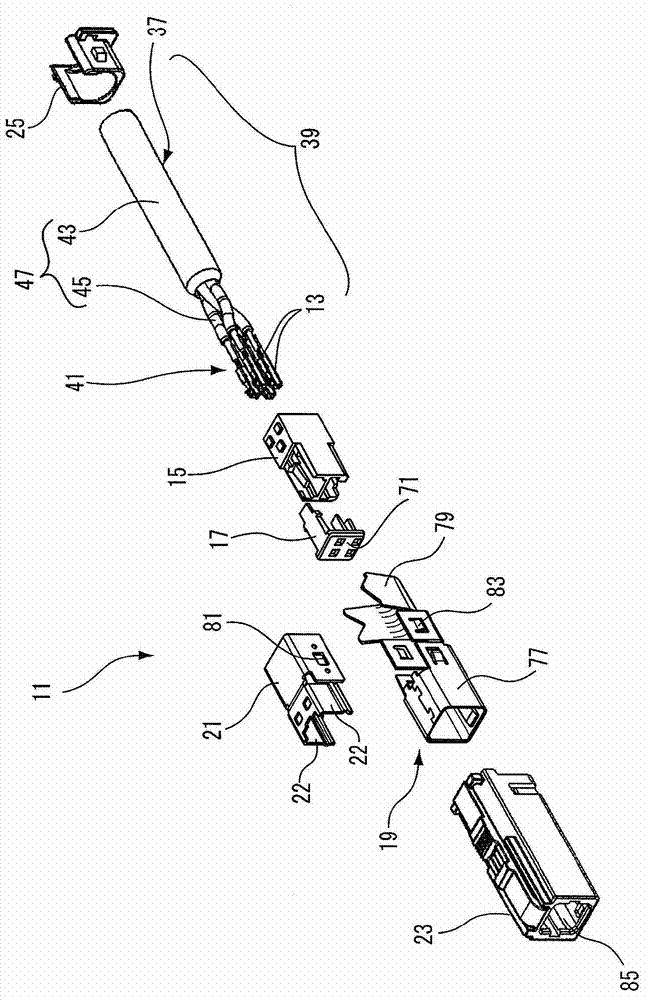
[0032] Such as figure 1 As shown, the shielded connector 11 includes a terminal 13 , an inner housing 15 , a front retainer 17 , a shield shell 19 , a shield shell cover 21 , an outer shell 23 and a rear retainer 25 .

[0033] The terminals 13 are machine molded from sheet metal. In this embodiment, each terminal 13 is a Figure 7 The female terminal of the box-shaped electrical contact portion 27 is shown. A contact piece 29 is formed inside the electrical contact portion 27, and the contact piece 29 is connected to the Figure 8 The tab 31 of the mating male terminal shown in B contacts. A terminal bent portion 35 to be locked with a hou...


PUM


Abstract

A shielded connector includes an inner housing to which terminals connected to a shielded electric wire is attached, a shield shell that includes a shield part and a barrel part, and a shield shell cover that covers a shielded wire exposure part of the shielded electric wire. The shield shell cover has a pair of insertion lap parts which are inserted between two side surfaces of the inner housing and two side surfaces of the shield part. A backlash preventing unit is provided on a top surface and a bottom surface of the inner housing and parts of the shield part which opposite to the top surface and the bottom surface of the inner housing so as to prevent a shaking between the inner housing and the shield shell.

Description

technical field [0001] The invention relates to a shielded connector. Background technique [0002] There is known a shielded connector: it is connected to a multi-strand shielded cable having a plurality of signal wires, wherein a conductor in which a plurality of metal wires are twisted together is covered with an insulating armor layer (for example, refer to JP-A-6-223909 and JP-A-2001-332356). [0003] For example, a shielded connector disclosed in JP-A-2001-332356 includes: a plurality of terminals connected to signal wires exposed at the end of a shielded cable; an insulator (inner case) accommodating and holding these terminals; The shielding metal cover (shielding case and shielding case cover) on the outside of the terminal and all exposed parts of the wire connection part of the terminal and the signal line; and the insulating cover shell (outer shell) attached to the outside of the shielding metal cover. [0004] The above-mentioned shielding metal cover has, fo...

Claims


Application Information

Patent Timeline
Patent Type & Authority Applications(China)
IPC IPC(8): H01R13/502H01R13/648
CPCH01R13/6593
Inventor 井伊良介
Owner YAZAKI CORP
Why Eureka
Try Eureka