Ultrasonic sensor

A sensor, ultrasonic technology, applied in the field of ultrasonic sensors

Inactive Publication Date: 2013-01-30
DENSO CORP
View PDF3 Cites 2 Cited by
  • Summary
  • Abstract
  • Description
  • Claims
  • Application Information

AI Technical Summary

Problems solved by technology

[0006] However, in conventional ultrasonic sensors, when changing the protruding length of the microphone, it is necessary to change the lengths of the connec

Method used


Image

  • Ultrasonic sensor
  • Ultrasonic sensor
  • Ultrasonic sensor

Examples


Embodiment Construction

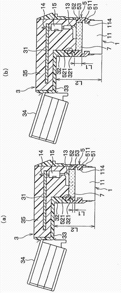
[0019] One embodiment of the present invention will be described. The ultrasonic sensor of this embodiment is mounted on a bumper of a vehicle and used as a rear sonar or a corner sonar. figure 1 (a) is a front view showing an ultrasonic sensor having a short microphone protrusion length according to an embodiment of the present invention in a partial section, figure 1 (b) is a front view of an ultrasonic sensor having a long microphone protrusion length according to an embodiment of the present invention, which is partially cross-sectionally shown.

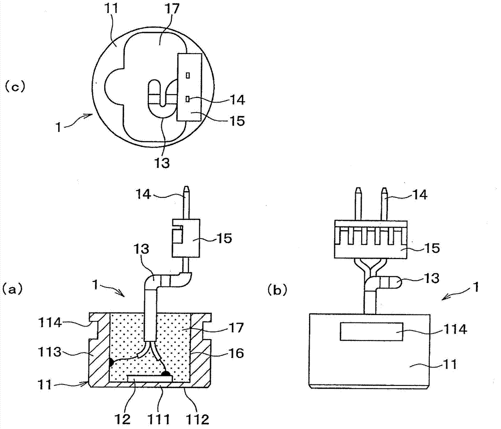
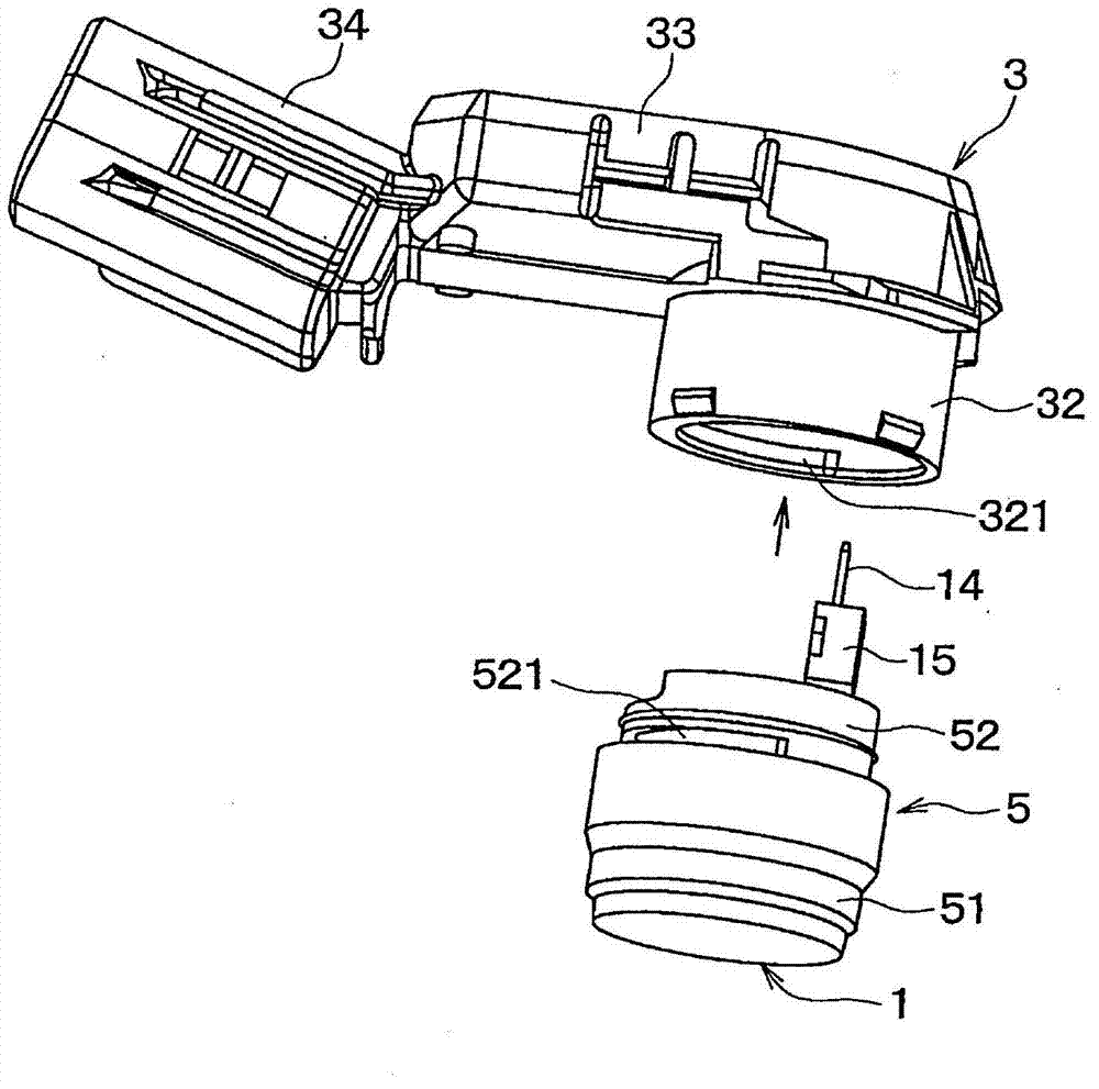
[0020] Such as figure 1 As shown, the ultrasonic sensor has: a piezoelectric element 12 (refer to figure 2 ), the case 3 housing the circuit board 31 electrically connected to the microphone 1 , the cylindrical connection member 5 connecting the microphone 1 and the case 3 , and the like.

[0021] figure 2 (a) is represented by a partial section figure 1 Front view of microphone 1, figure 2 (b) is figure 2 (a) Side vie...


PUM


Abstract

The invention relates to an ultrasonic sensor. A connecting component (5) connecting a microphone (1) and a housing (3) has a holding cylinder portion (51) for holding the microphone (1), an embedding cylinder portion (52) embedded with the housing (3), and an intermediate cylinder portion (53) formed between the holding cylinder portion (51) and the embedding cylinder (52). By this means, a protrusion length (L2) of the microphone can be changed only through changing a length (L1) of the intermediate cylinder portion (53) in the connecting components (5), that is, through the replacement of the connecting component (5).

Description

technical field [0001] The present invention relates to an ultrasonic sensor including a microphone having a piezoelectric element. Background technique [0002] Conventional ultrasonic sensors are mounted on, for example, a bumper of a vehicle, transmit ultrasonic waves, and receive reflected waves reflected by obstacles to detect obstacles near the bumper. [0003] As such an ultrasonic sensor, for example, there is a technique disclosed in Patent Document 1 (Japanese Patent Application Laid-Open No. 2007-251534 ). The ultrasonic sensor disclosed in this patent document 1 includes a microphone in which a piezoelectric element is housed in a case, and a case in which a circuit board is housed. The microphone is electrically connected to the circuit board through connecting pins drawn out from the housing. [0004] Furthermore, in the case, the case cylindrical portion protrudes from the case main body portion that accommodates the circuit board, and the microphone is inse...

Claims


Application Information

Patent Timeline
IPC IPC(8): G01S7/521
Inventor 田中昭太朗川岛康裕清水忠夫
Owner DENSO CORP
Why Eureka
Try Eureka