
Spindle motor

a spindle motor and spindle technology, applied in the direction of structural association, undesired vibration/sound insulation/absorption, dynamo-electric machines, etc., can solve the problems of increasing serious problems caused by vibration, affecting the reliability of reading and writing data, and occurrence of vibration, so as to suppress the transmission of vibrations and reduce the occurrence.

Inactive Publication Date: 2012-06-12
SAMSUNG ELECTRO MECHANICS CO LTD
View PDF17 Cites 1 Cited by
  • Summary
  • Abstract
  • Description
  • Claims
  • Application Information

AI Technical Summary

Benefits of technology

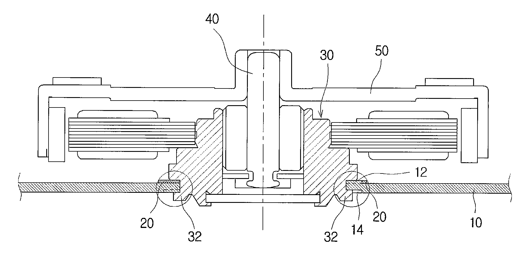
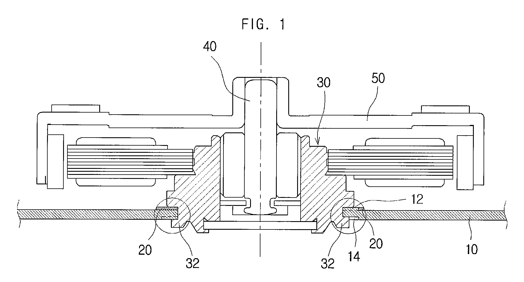
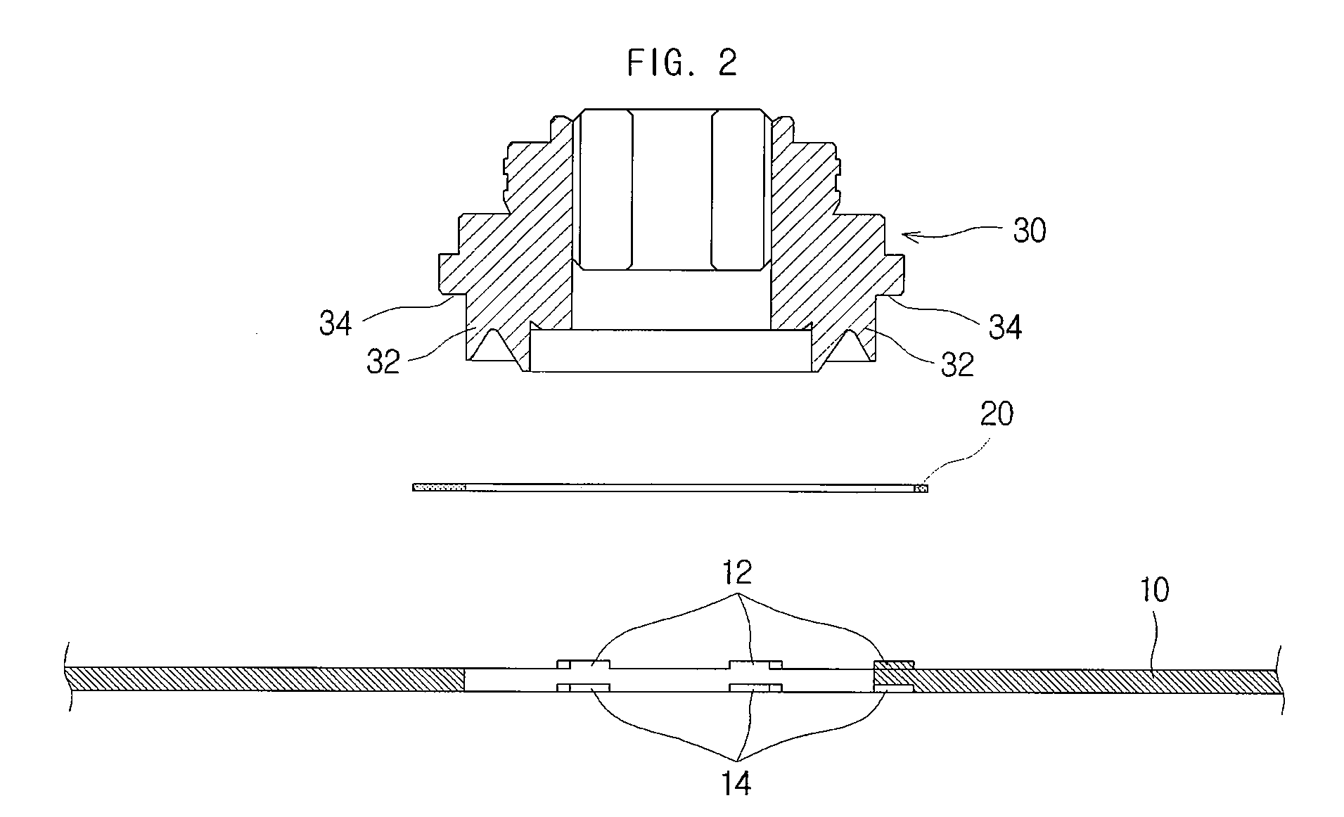
The invention provides a spindle motor that reduces vibrations during operation. The motor includes a rotor support piece, a base plate, and a buffer member. The rotor support piece rotatably supports a rotor and has a mounting part that is inserted into the base plate. The buffer member is positioned between the rotor support piece and the base plate to absorb vibration. The support protrusions on the base plate support the mounting part along its periphery. The support protrusions and protrusion cavities can be formed by a pressing process. The insertion hole has a circular shape and the support protrusions are evenly spaced around its perimeter. The technical effect of this invention is to reduce vibration during spindle motor operation.

Problems solved by technology

When a spindle motor undergoes rotation, however, various factors, such as defects in the spindle motor parts, eccentricity in the assembly of the disk, and irregular airflow within the disk drive, may lead to the occurrence of vibration.
Such vibration is liable to cause track misregistration (TMR), and hence to an increase in position error signals (PES), resulting in lower reliability in reading and writing data.
Problems caused by vibration have become increasingly serious due to the rapid increase of data density in the disk.
In particular, if a base plate is rigidly coupled to the rotor, the vibration may be transferred to the encoder, etc., that reads signals from the disk, leading to even more serious problems.

Method used


Image

  • Spindle motor
  • Spindle motor
  • Spindle motor

Examples


Embodiment Construction

[0025]As the invention allows for various changes and numerous embodiments, particular embodiments will be illustrated in the drawings and described in detail in the written description. However, this is not intended to limit the present invention to particular modes of practice, and it is to be appreciated that all changes, equivalents, and substitutes that do not depart from the spirit and technical scope of the present invention are encompassed in the present invention.

[0026]While such terms as “first” and “second,” etc., may be used to describe various components, such components must not be limited to the above terms. The above terms are used only to distinguish one component from another.

[0027]The terms used in the present specification are merely used to describe particular embodiments, and are not intended to limit the present invention. An expression used in the singular encompasses the expression of the plural, unless it has a clearly different meaning in the context. In t...


PUM

PropertyMeasurementUnit
thicknessaaaaaaaaaa
perimeteraaaaaaaaaa
data densityaaaaaaaaaa

Abstract

A spindle motor can include a rotor support piece, which may rotatably support a rotor that is inserted onto one end, and which may include a projecting part that protrudes from the other end and a mounting part that has a flat surface formed along the periphery of the projecting part; a base plate, in which an insertion hole may be formed for inserting the projecting part through, and on which multiple support protrusions may be formed along the periphery of the insertion hole for supporting the mounting part along a periphery of the insertion hole; and a buffer member, which may include a projecting-part hole for inserting the projecting part through and support-protrusion holes for inserting the support protrusions through, and which may be positioned between the rotor support piece and the base plate to absorb vibration. This arrangement can reduce the occurrence and transfer of vibrations.

Description

CROSS-REFERENCE TO RELATED APPLICATIONS[0001]This application claims the benefit of Korean Patent Application No. 10-2008-0127486, filed with the Korean Intellectual Property Office on Dec. 15, 2008, the disclosure of which is incorporated herein by reference in its entirety.BACKGROUND[0002]1. Technical Field[0003]The present invention relates to a spindle motor.[0004]2. Description of the Related Art[0005]A spindle motor is commonly used as an apparatus for rotating a mounted disk, and may be used in various devices such as optical disk drives, magnetic disk drives, and hard disk drives.[0006]When a spindle motor undergoes rotation, however, various factors, such as defects in the spindle motor parts, eccentricity in the assembly of the disk, and irregular airflow within the disk drive, may lead to the occurrence of vibration.[0007]Such vibration is liable to cause track misregistration (TMR), and hence to an increase in position error signals (PES), resulting in lower reliability ...

Claims


Application Information

Patent Timeline
Patent Type & Authority Patents(United States)
IPC IPC(8): H02K5/16H02K5/24G11B33/08
CPCH02K5/163H02K5/24H02K5/16H02K5/04
Inventor SMIRNOV, VIATCHESLAV
Owner SAMSUNG ELECTRO MECHANICS CO LTD
Learn More