Cover member fastening method and fastening structure for a head cover

A technology for cylinder head cover and cover parts, which is applied to engine components, engine sealing, engine sealing devices, etc., can solve the problems of poor vibration and noise prevention effect, difficult abutting parts, and difficulty in maintaining uniform sealing surfaces, and achieves suppression of The effect of vibration transmission, reduction of contact area, and reduction of vibration transmission

Inactive Publication Date: 2012-07-04
HONDA MOTOR CO LTD
View PDF5 Cites 1 Cited by
  • Summary
  • Abstract
  • Description
  • Claims
  • Application Information

AI Technical Summary

Problems solved by technology

[0003] However, the floating structure of the rubber gasket is not appropriate when there is an abutment portion required for more secure abutment fixation between the cylinder head cover and the upper surface of the cylinder head.
On the other hand, although the sealing structure of the liquid packing is suitable for fixing the abutting part, the sealing structure of the liquid packing is not only inferior to the rubber gasket in terms of vibration and noise prevention effect, but also for the cylinder head cover that needs to be disassembled and replaced during maintenance, such as the cylinder head cover. It is difficult to maintain a uniform sealing surface for parts that perform sealing peeling and recoating, so it is difficult to strictly control the gap between the abutting parts

Method used


Image

  • Cover member fastening method and fastening structure for a head cover
  • Cover member fastening method and fastening structure for a head cover
  • Cover member fastening method and fastening structure for a head cover

Examples


Embodiment Construction

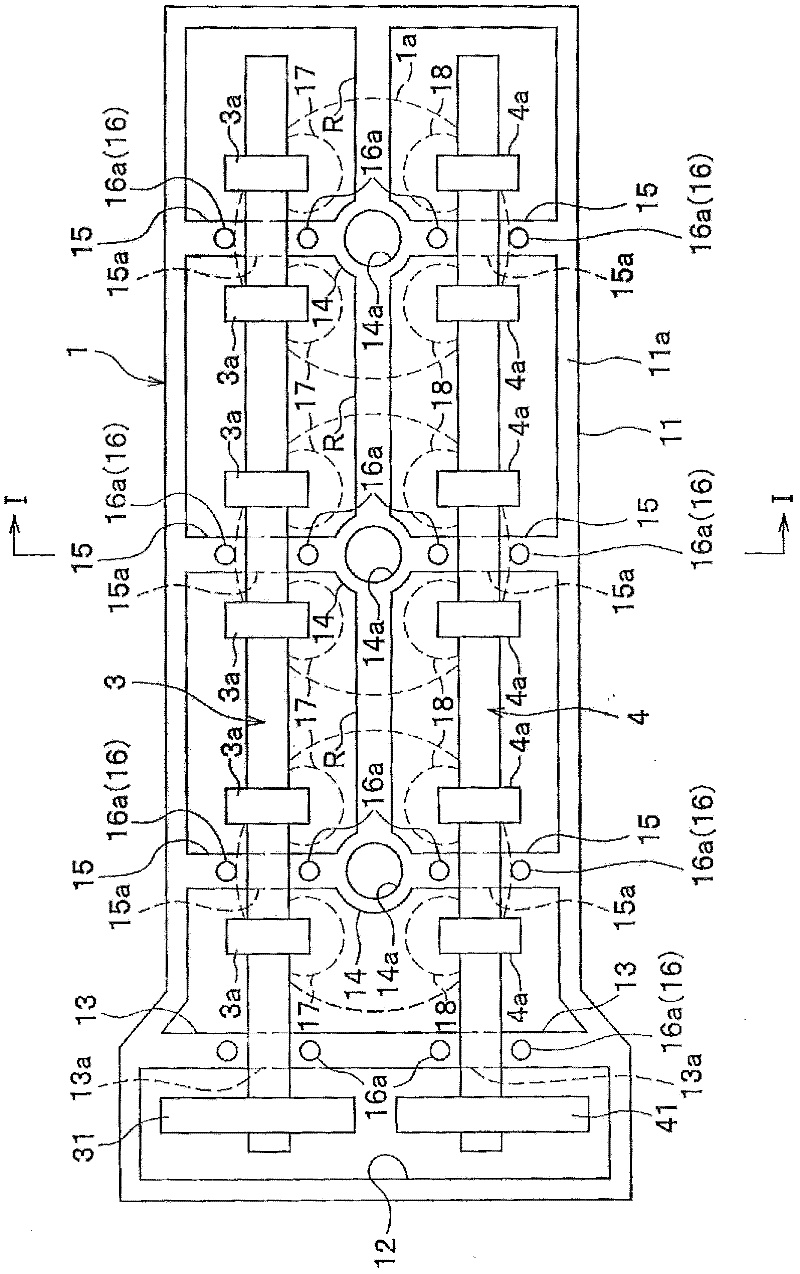
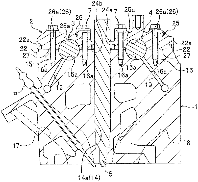
[0034] Embodiments of the present invention will be described in detail with reference to the drawings. In the description, the same reference numerals are assigned to the same elements, and overlapping descriptions are omitted. Also, when directions are shown in the description, sometimes the figure 1 The shown axial direction of the camshafts 3 and 4 is referred to as the longitudinal direction, and the direction perpendicular to the axis is referred to as the lateral direction. And, will figure 1 The axial direction (direction perpendicular to the paper surface) of the shown combustion chamber 1a will be described as the vertical direction.

[0035] Such as figure 1 , figure 2As shown, a cylinder head 1 is a part of an inline three-cylinder engine, and holds an intake-side camshaft 3 and an exhaust-side camshaft 4 in a rotatable manner. Around the cylinder head 1, an outer peripheral wall 11 is provided in a square frame shape, and a cylinder head side mounting surfac...


PUM


Abstract

Provided are a cover member fastening method and a fastening structure whereby the surface area in contact with an engine body is decreased, minimizing the transmission of vibrations to the cover member. Said fastening method and fastening structure also minimize deformation of the cover member while securely affixing abutting parts that need to be firmly fixed in place. The provided fastening structure uses a fastening member (7) to fasten a head cover (2) to a cylinder head (1) so as to cover the top surface of said cylinder head (1). Abutting parts (27) that abut against the top surface of the cylinder head (1) are formed on the inside surface of the head cover (2). The bottom surfaces of head-cover-side fastening boss parts (26) protrude farther than the bottom surface of a head-cover-side attachment flange (22). The surface area (A) of the bottom surfaces of the head-cover-side fastening boss parts (26) equals or approximates a minimum contact area (Amin) obtained by dividing the required axial fastening force (N) of the fastening member (7) by a stress tolerance (sa) determined by the material that the head cover (2) is made of.

Description

technical field [0001] The present invention relates to a fastening method of a cover member and a fastening structure of a cylinder head cover of an internal combustion engine. Background technique [0002] Conventionally, as a sealing structure of a cylinder head cover of an internal combustion engine, a sealing structure using a liquid filler and a sealing structure using a rubber gasket are known. From the viewpoint of preventing noise caused by transmission of vibration from the cylinder head to the cylinder head cover, it is preferable to employ a structure in which the head cover is floated and held by a rubber packing having a noise prevention effect better than that of a liquid filler. [0003] However, the floating structure of the rubber packing is not suitable when there is an abutting portion required for more firm abutting fixation between the cylinder head cover and the upper surface of the cylinder head. On the other hand, although the sealing structure of t...

Claims


Application Information

Patent Timeline
Patent Type & Authority Applications(China)
IPC IPC(8): F02F7/00F02F11/00F16J15/10
CPCF01L1/053F02F7/006F01L2001/0537F01L2103/00F01L2001/0476Y10T29/49231F01L2303/00
Inventor 三上祥平平山直人久野泰宏
Owner HONDA MOTOR CO LTD
Why Eureka
Try Eureka