
Base for low pressure discharge lamps

A technology for low-pressure discharge lamps and lamp caps, applied in discharge lamps, discharge tubes, circuits, etc., can solve the problems of flammability, complicated manufacturing process, poor thermal conductivity, etc., and achieve the effect of not being easy to catch fire

Inactive Publication Date: 2007-06-20
GENERAL ELECTRIC CO
View PDF7 Cites 0 Cited by
  • Summary
  • Abstract
  • Description
  • Claims
  • Application Information

AI Technical Summary

Problems solved by technology

One disadvantage is that the material used to make the entire lamp cap has poor thermal conductivity
Due to the poor thermal conductivity of the lamp head material, the lamp head does not adequately cool the cold spot
Another disadvantage is that due to the heat emitted by the lamp during lamp operation, the lamp cap made of thermoplastic can be deformed in this unfavorable situation
Another disadvantage is that the lamp cap made of thermoplastic is prone to aging and flammability
This makes the manufacturing process relatively complicated

Method used


Image

  • Base for low pressure discharge lamps
  • Base for low pressure discharge lamps
  • Base for low pressure discharge lamps

Examples


Embodiment Construction

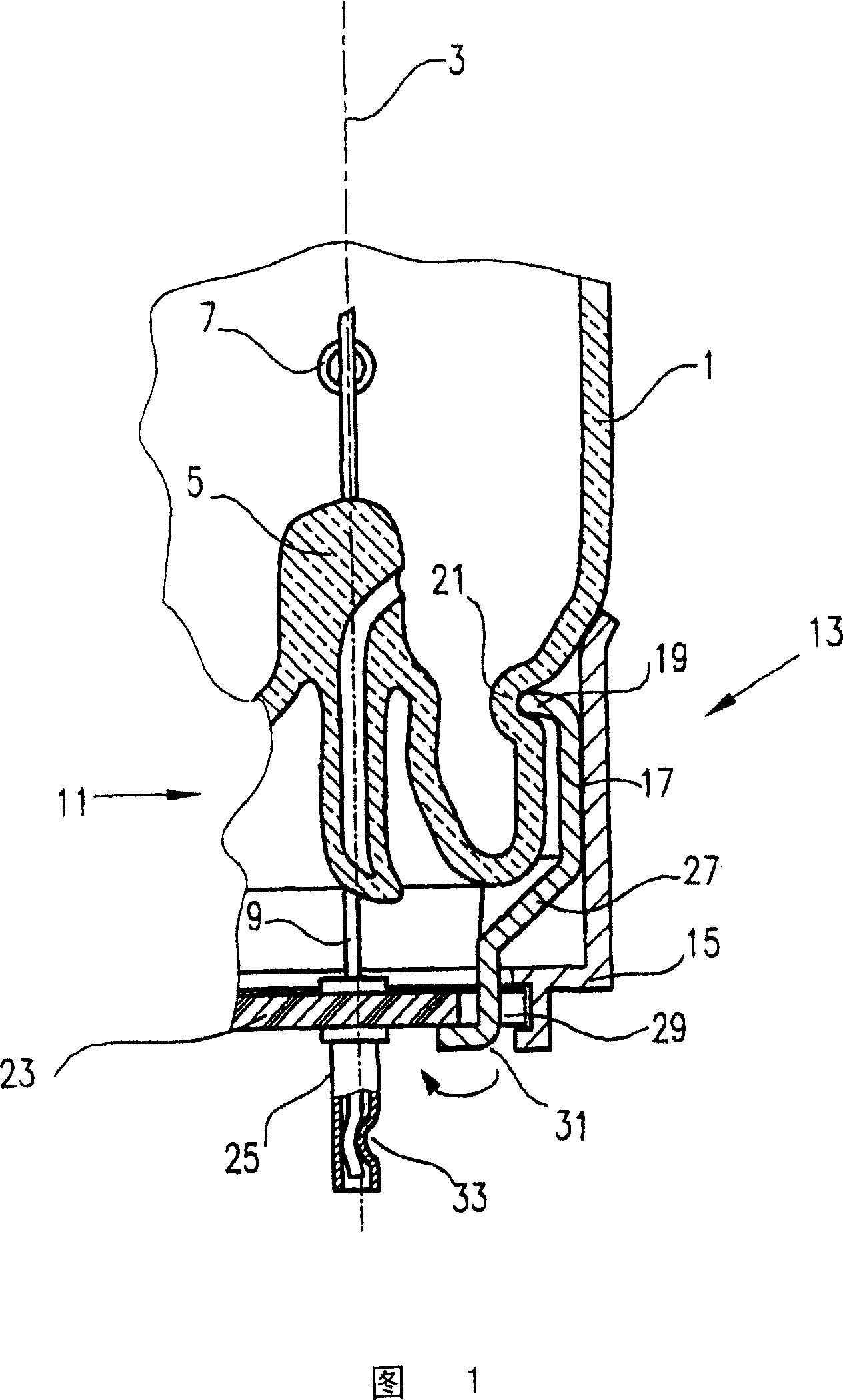
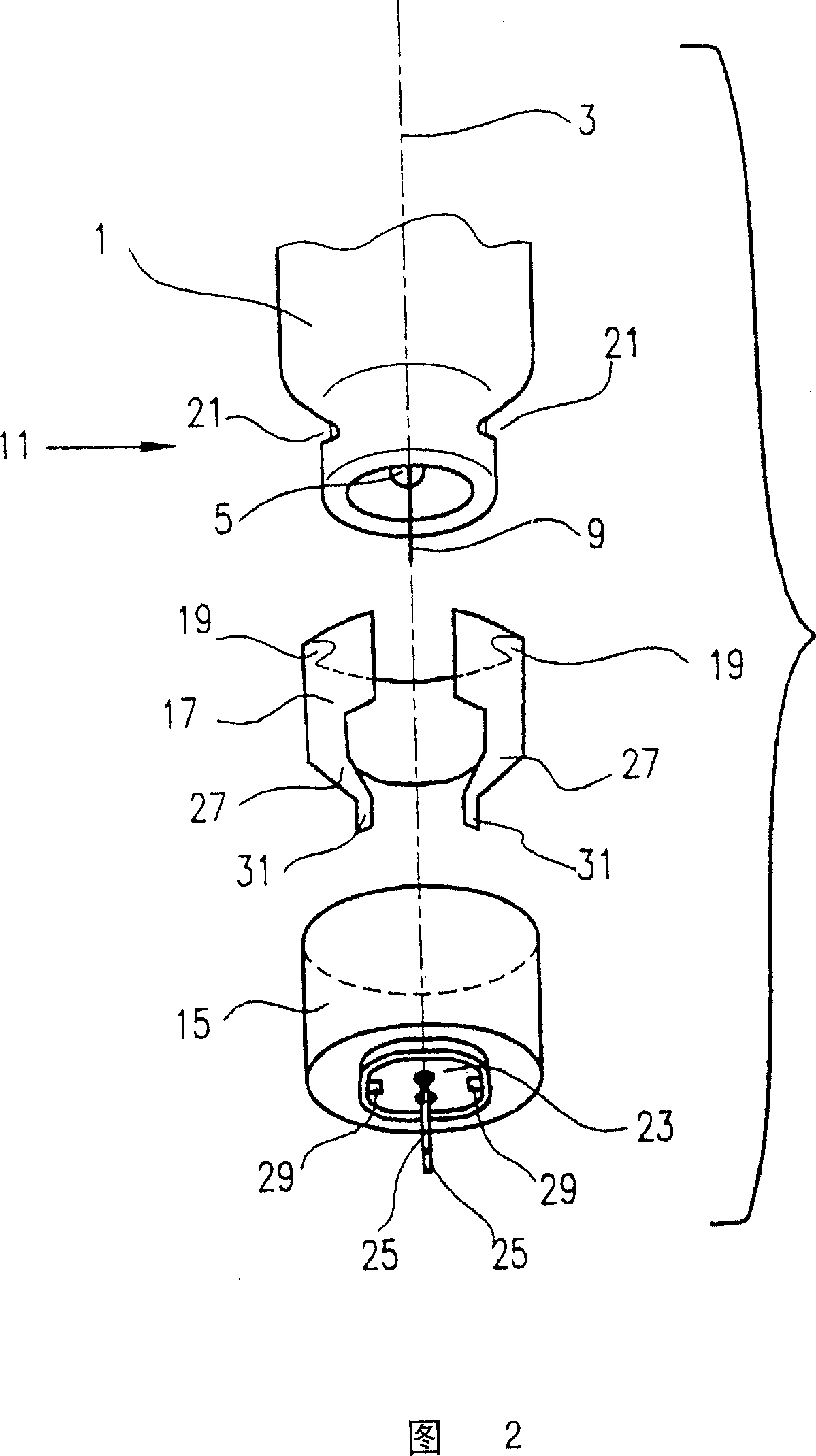
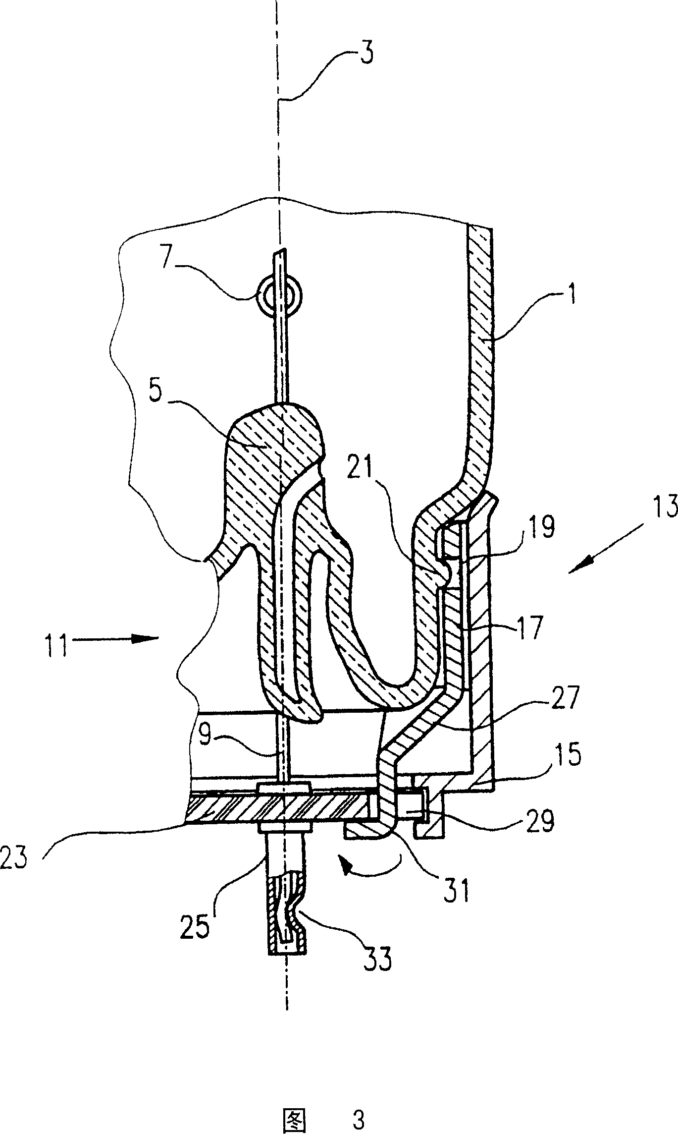
[0013] Referring now to Figure 1, there is shown a cap 13 mounted on one end of a low pressure discharge lamp. The lamp comprises a glass envelope 1 with an axis 3 . Although not shown in the figures, the capsule 1 is coated with phosphorus on its inner surface and filled with the inert gas and mercury required for the discharge, in a manner known to those skilled in the art. The capsule 1 is hermetically sealed and includes a rod-like portion 5 having a current lead-in terminal 9 embedded therein and an electrode 7 mounted thereon. In order to form the well-defined shape for the end of the low-pressure discharge lamp, the seal is made by using a mold during the glass melting process. This shape is characterized by a sealing zone 11 extending axially from the capsule 1 , which is smaller in diameter than the capsule 1 . The base 13 fitted to the sealing area 11 comprises a base housing 15 made of metal, for example aluminium. An insulator 23 made of fiberglass plastic is at...


PUM


Abstract

A lamp base (13) in combination with a low pressure discharge lamp is provided. The low pressure discharge lamp comprises a glass envelope (1) which has an end portion and an axis (3). A stem (5) is melted into the end portion of the envelope in a gas-tight manner in order to form a seal region (11). The stem is mounted with an electrode and includes a current in-lead which is connected to the electrode. The lamp base comprises a metallic base shell (15) which is fitted to the seal region (11). A resilient insert (17) is disposed substantially in the base shell. Said resilient insert embraces the seal region at least partly, and fits resiliently to an interior surface of the base shell. Said insert as means suitable for positioning the lamp base in cooperation with further means formed on the surface of the seal region. The base shell has an end portion closed at least partly by an insulator piece 23) which embeds a base stud (25) made of metal. The base stud is connected to the current in-lead (9).

Description

technical field [0001] The invention relates to a lamp cap for a low-pressure discharge lamp, in particular to a lamp cap structure, which enables the lamp cap to be fixed on the lamp envelope without using lamp cap bonding agent. Background technique [0002] The base of a low-pressure discharge lamp provides an electrical and mechanical connection for the lamp to a socket. Generally, a lamp cap comprises a metal or plastic cap cap fitted to the end of the lamp envelope and a plurality of contacts responsible for electrically and mechanically connecting the lamp to the socket. If the cap shell is made of metal, the ends of the cap shell are closed by insulating discs which are embedded in one or two cap contact posts to which the lamp leads are electrically fixed. [0003] US Patent No. 4221453 discloses a low-pressure discharge vessel having a cap made of elastic, flexible thermoplastic. The base housing has an annular wall with inwardly projecting knuckles. When the la...

Claims


Application Information

Patent Timeline
Patent Type & Authority Patents(China)
IPC IPC(8): H01J5/60H01J5/50
CPCH01J5/60
Inventor G·布赛G·霍尔瓦斯
Owner GENERAL ELECTRIC CO
Learn More