Die press quenching device for fully quenching steel ferrules

A molded quenching and steel sleeve technology, applied in the direction of quenching devices, furnace types, furnaces, etc., can solve the problems of inapplicable products of various sizes, high rework and scrap rate, uncontrollable quenching process, etc., to achieve quenching technology and control The effect of technology improvement, short quenching time and small deformation

Active Publication Date: 2013-12-18
NINGXIA MACHINERY RES INST
View PDF6 Cites 3 Cited by
  • Summary
  • Abstract
  • Description
  • Claims
  • Application Information

AI Technical Summary

Problems solved by technology

In order to solve the problems of uncontrollable quenching process of through-hardened steel bearing rings, rework caused by irregular deformation and high reject rate, people have done a lot of work, such as the inventor in the utility model patent ZL200420086806. A multi-station quenching press is designed in "Quenching Press Machine for Inner and Outer Rings of Bearings", which partially solves the problem of quenching deformation of bearing rings
However, it is difficult to adjust the press quenching force in engineering applications, and it cannot be applied to products of various sizes. After quenching, the workpiece has local soft spots and quenching quality problems, etc.

Method used


Image

  • Die press quenching device for fully quenching steel ferrules
  • Die press quenching device for fully quenching steel ferrules
  • Die press quenching device for fully quenching steel ferrules

Examples


Embodiment Construction

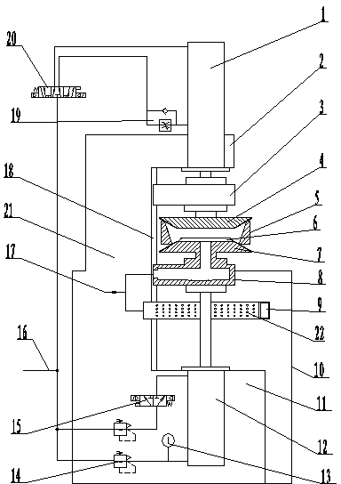
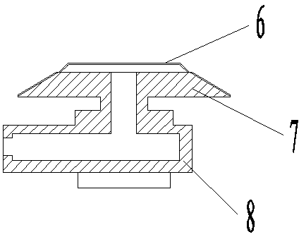
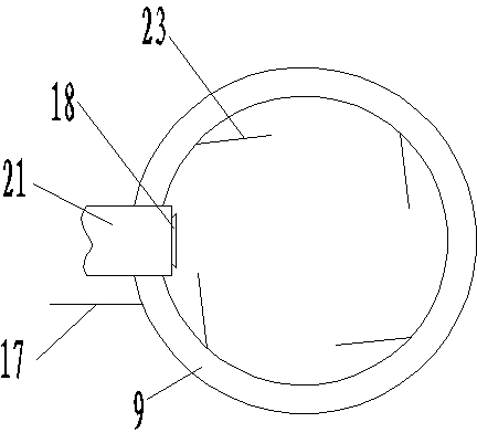
[0015] In the figure, 1-upper mold cylinder, 2-beam, 3-upper slider, 4-upper mold, 5-workpiece to be quenched, 6-shroud, 7-lower mold, 8-lower slider, 9-spray Oil ring, 10—oil pool, 11—base, 12—lower mold cylinder, 13—precision pressure gauge, 14—pressure regulating valve, 15—reversing valve II, 16—high pressure pipeline, 17—cooling oil pipe, 18 —Guide rail, 19—one-way speed control valve, 20—reversing valve 1, 21—column, 22—the fuel injection port on the injection ring, 23—baffle plate.

[0016] like figure 1 , 2 , 3, the bed of this device is made up of a base 11, a column 21 installed on the left side of the base and a beam 2 installed on the upper end of the column, the base is installed in the oil pool 10, and a vertical Guide rail 18, upper slider 3 and lower slider 8 are respectively installed on the guide rail, upper mold cylinder 1, lower mold cylinder 12 are respectively fixed on the beam and the base, and the axes of upper and lower mold cylinders coincide, upper ...


PUM


Abstract

The invention relates to a heat treatment quenching device, in particular to a die press quenching device for fully quenching steel ferrules. The die press quenching device comprises a base, a stand column at one side of the base and a cross beam at the upper end of the stand column, wherein an upper sliding block and a lower sliding block are respectively arranged on a guiding rail of the stand column, and piston rods of an upper die cylinder and a lower die cylinder are respectively connected with the upper sliding block and the lower sliding block. The die press quenching device is characterized in that a high-pressure pipeline is connected with the upper die cylinder and the lower die cylinder respectively, a one-way speed regulating valve and a reversing valve I, which are used for controlling the speed and the direction of the upper die cylinder, are respectively arranged on a high pressure pipeline connected with the upper die cylinder, a pressure regulating valve and a reversing valve II, which are used for controlling the pressure and the direction of the lower die cylinder, are respectively arranged on a high pressure pipeline connected with the lower die cylinder, and cooling oil for quenching is connected with an oil outlet and an oil spraying ring on the lower die. According to the device, the press quenching force and the press quenching speed can be precisely regulated, the quenching time is short, the deformation of quenched workpieces is small, the quenching quality is effectively ensured, and existing quenching and controlling technologies are greatly improved.

Description

technical field [0001] The invention relates to a heat treatment quenching device, in particular to a press quenching device for through-hardening steel ferrules. Background technique [0002] The inner and outer rings of bearings are generally made of two materials, one is low-carbon low-alloy steel, which needs to be carburized and quenched, which is called carburized steel in the industry; most bearing materials are high-carbon chromium steel, represented by GCr15, and the industry Called through-hardened steel. Compared with carburizing steel: 1) Through-hardening steel can be directly heated and quenched, with short heating time and small deformation; 2) It is more sensitive to the quenching time, and requires a shorter residence time before quenching; 3) Quenching deformation varies with The shape and size of the workpiece change, and there is no fixed rule. In order to solve the problems of uncontrollable quenching process of through-hardened steel bearing rings, re...

Claims


Application Information

Patent Timeline
Patent Type & Authority Applications(China)
IPC IPC(8): C21D9/40C21D11/00C21D1/673
Inventor 张光荣王国升周建宇王淑芳柳燕许军晓张凯翔
Owner NINGXIA MACHINERY RES INST
Why Eureka
Try Eureka