
Modularized vibrating screen

A vibrating screen, modular technology, applied in the fields of filter screen, chemical instrument and method, solid separation, etc., can solve the problems such as difficulty in transporting the screen to industrial site, difficult transportation of large vibrating screen, high transportation cost, etc. Reduced difficulty, improved shock absorption, and easy upscaling

Inactive Publication Date: 2014-11-05
四川科立科技发展有限公司
View PDF5 Cites 0 Cited by
  • Summary
  • Abstract
  • Description
  • Claims
  • Application Information

AI Technical Summary

Problems solved by technology

[0005] On the other hand, due to the restrictions of roads, bridges, culverts, and vehicles, the transportation of large vibrating screens is very difficult
It is difficult for us to imagine how a 5-meter, 6-meter, 7-meter or even wider sieve can be transported to the industrial site for use
Due to the difficulty of transportation, it also leads to extremely high transportation costs

Method used


Image

  • Modularized vibrating screen
  • Modularized vibrating screen
  • Modularized vibrating screen

Examples


Embodiment 1

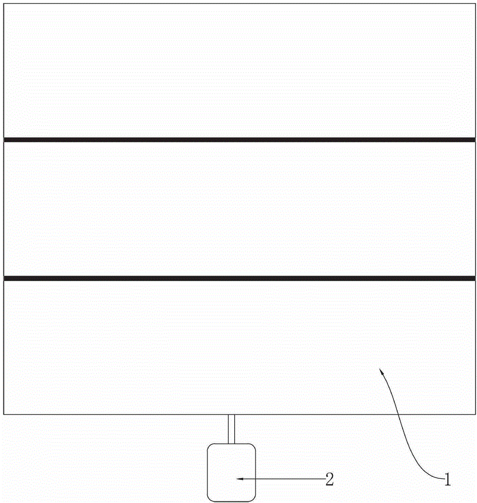
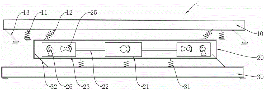
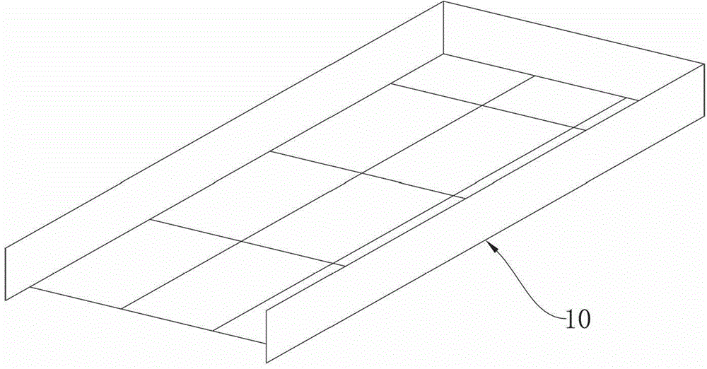
[0034] see Figure 1 to Figure 11 . The modular vibrating screen described in this embodiment includes a power input device, that is, a motor 2, and three unit modules 1, such as figure 1 shown. Each unit module 1 comprises a frame 30, a power layer 20 is installed above the frame 30, and a working layer 10, i.e. a screen box, is installed above the power layer 20, such as figure 2 shown. Power is transmitted between the working layer 10 and the power layer 20 through the spring device 12 , and the power transmission direction is the direction in which the spring device 12 expands and contracts. The upper end of the spring device 12 is fixedly connected with the working layer, and the lower end is fixedly connected with the power layer. The preferred angle between the spring device 12 and the power layer 20 is 45°. The working layer 10 is also connected to the ground through the first leaf spring 13 and connected to the ground through the damping spring 11 . Figure 9 A...

Embodiment 2

[0042] Different from Embodiment 1, the structure of the power layer 20 in this embodiment is a cross-shaped frame, such as Figure 12 shown. Correspondingly, the eccentric device can choose to use eccentric block or eccentric wheel. Figure 12 A form of installation of the eccentric device is shown, that is, the first eccentric mass 25' and the second eccentric mass 26' are directly fastened on the output shaft of the second reversing box 23. During installation, the angle between the two eccentric blocks needs to be set, preferably 90°.


PUM


Abstract

The invention discloses a modularized vibrating screen. The modularized vibrating screen comprises more than one unit module. Each unit module comprises a rack. A motive power layer is installed above the rack and a working layer is installed above the motive power layer. A motive power shaft, a first inverting box, a connector and a second inverting box of the motive power layer are connected in sequence. The second inverting box comprises two pairs of output shafts. A first eccentric gear and a second eccentric gear are fixedly installed on each pair of the output shafts. The connection line between the center of gravity and the center of axis of the first eccentric gear is vertical to the connection line between the center of gravity and the center of axis of the second eccentric gear. Motive power is transmitted between the working layer and the motive power layer through a spring device. The working layer is fixed on the rack or on a ground through a first plate spring. The spring device is vertical to the first plate spring. Compared with the prior art, the modularized vibrating screen is low in energy consumption, little in vibration and noise, easy to upsize, convenient to transport, not only suitable for coal dressing and mineral separation industries, but also suitable for the industries which need grading and dewatering, such as the chemical industry and the iron and steel industry, and wide in application area.

Description

technical field [0001] The invention belongs to a vibration machine, in particular to a large modular vibration equipment. Background technique [0002] my country is a big energy country, both a big producer and a big consumer. The efficient use of resources has become an important national strategy. The national development plan has brought great development opportunities to the vibration machinery industry. The central government has clearly pointed out in the "Outline of the Eleventh Five-Year Plan for National Economic and Social Development" that it is necessary to develop major technical equipment with great influence, including large-scale metallurgical equipment, large-scale screening and washing equipment, etc. The Twelfth Five-Year Plan of the coal preparation industry also proposes that the raw coal processing capacity of a single machine is 10 million tons per year. Therefore, the system puts forward very high requirements for the large-scale single equipment, ...

Claims


Application Information

Patent Timeline
Patent Type & Authority Patents(China)
IPC IPC(8): B07B1/28B07B1/42
Inventor 唐志
Owner 四川科立科技发展有限公司
Learn More