
Wireless communication method, wireless communication apparatus and wireless communication system

A technology of a wireless communication device and a wireless communication system, applied in wireless communication, signal transmission system, machine-to-machine/machine-type communication service, etc., capable of solving problems such as decreased data transmission efficiency and increased system overhead

Inactive Publication Date: 2015-04-15
FUJITSU LTD
View PDF3 Cites 0 Cited by
  • Summary
  • Abstract
  • Description
  • Claims
  • Application Information

AI Technical Summary

Problems solved by technology

[0011] However, there is a problem that, when the wireless communication device intermittently transmits data, when the connection is established and released every time the data is transmitted, the system overhead caused by the steps of establishing and releasing the connection becomes large, and the data transmission time is increased. Efficiency drops

Method used


Image

  • Wireless communication method, wireless communication apparatus and wireless communication system
  • Wireless communication method, wireless communication apparatus and wireless communication system
  • Wireless communication method, wireless communication apparatus and wireless communication system

Examples


no. 1 Embodiment approach ]

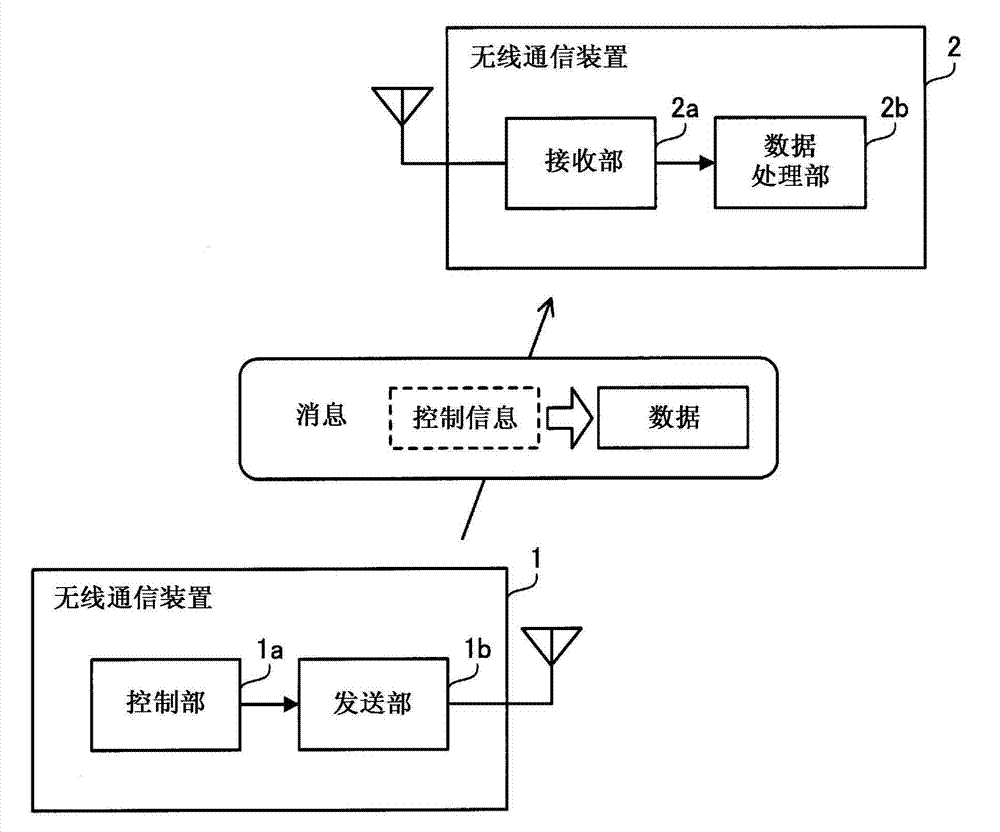
[0031] figure 1 It is a diagram showing the radio communication system of the first embodiment. The wireless communication system according to the first embodiment includes wireless communication devices 1 and 2 . For example, it is considered that the wireless communication device 2 is installed as a base station, and the wireless communication device 1 is installed as a participant station for accessing the wireless communication device 2 . The wireless communication device 1 transmits data to the wireless communication device 2 through wireless communication. The wireless communication devices 1 and 2 can appropriately establish and release a wireless communication connection.

[0032] The radio communication device 1 includes a control unit 1a and a transmission unit 1b. When the connection between the wireless communication devices 1 and 2 is not established, the control unit 1a determines the timing at which control information can be transmitted to the wireless commu...

no. 2 Embodiment approach ]

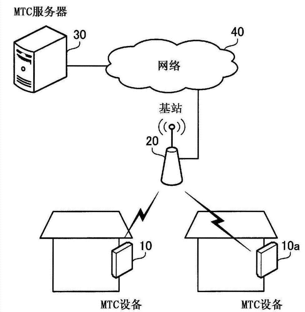
[0041] figure 2 It is a figure showing the wireless communication system of 2nd Embodiment. The wireless communication system of the second embodiment includes MTC devices 10 , 10 a , a base station 20 , an MTC server 30 , and a network 40 . The base station 20 is capable of data communication with the MTC server 30 via the network 40 .

[0042] The MTC devices 10 and 10a are wireless communication devices connected to meters installed in homes and offices. As the measuring meter, a gas meter, an electric meter, a water meter, etc. are considered. The MTC devices 10, 10a access the base station 20, and transmit various data including MTC data representing the measured value of the meter to the MTC server 30 via the base station 20. It is expected that the amount of MTC data sent by the MTC device 10, 10a at one time is small. In addition, it is expected that the cycle of sending MTC data is a cycle as long as a one-month cycle.

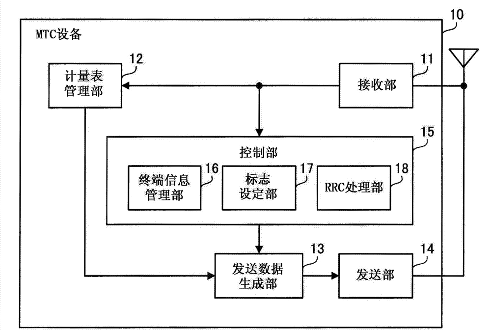
[0043] In addition, the MTC device 10 has...


PUM


Abstract

Overhead of radio communication is suppressed and data is efficiently transmitted. A first radio communication apparatus (1) includes a controller (1a) and a transmitter (1b). The controller (1a) determines timing capable of transmitting a control parameter used for a process for establishing connection to a second radio communication apparatus (2) when the connection is not established between the first and second radio communication apparatus (1, 2). The transmitter (1b) transmits a message including data different from the control parameter to the second radio communication apparatus (2) at determined timing. The second radio communication apparatus (2) includes a receiver (2a) and a data processing unit (2b). The receiver (2a) receives from the first radio communication apparatus (1) the message transmitted at timing at which the first radio communication apparatus (1) is able to transmit the control parameter. The data processing unit (2b) extracts data included in the received message.

Description

technical field [0001] The present invention relates to a wireless communication method, a wireless communication device and a wireless communication system. Background technique [0002] Currently, wireless communication systems such as mobile phone systems are widely used. In addition, in order to further increase the speed and broadband of wireless communication, research on next-generation wireless communication technology is continuously and actively conducted. For example, 3GPP (3rd Generation Partnership Project: 3rd Generation Partnership Project), which is one of the standardization groups, proposes a wireless communication system called LTE (Long Term Evolution, Long Term Evolution) and a wireless communication system developed from LTE. A wireless communication system called LTE-A (Long Term Evolution-Advanced, LTE-Advanced) (see, for example, Non-Patent Documents 1 and 2). [0003] Such a wireless communication technology can be used not only for wireless commu...

Claims


Application Information

Patent Timeline
Patent Type & Authority Patents(China)
IPC IPC(8): H04W4/20
CPCH04W28/06H04W76/023G08C17/00H04W72/12H04W76/14H04W4/70
Inventor 田岛喜晴田中良纪河崎义博太田好明杉山胜正大渕一央
Owner FUJITSU LTD
Learn More