Inclined sliding groove rail pair with self-locking flat surface

A technology of inclined chute and inclined sliding rail, applied in the field of groove rail auxiliary device, can solve the problems of low efficiency of unlocking and resetting and locking of inclined core block, increased mold maintenance cost, complicated mold structure, etc., so as to improve the efficiency , simplify the structure, overcome the effect of complex structure

Active Publication Date: 2013-02-20
NINGBO FANGZHENG TOOL
View PDF7 Cites 9 Cited by
  • Summary
  • Abstract
  • Description
  • Claims
  • Application Information

AI Technical Summary

Problems solved by technology

[0002] The groove rail pair is composed of a slider with a chute and a slider with a slide rail through sliding buckle connection, and is used to carry the sliding device of the internal parts of the injection mold; the groove rail pair is divided into straight sliding groove rail pair and oblique There are two types of chute rail pairs. The straight chute rail pair is equipped with a straight chute and slide rail. It is usually used for the foot of the inclined ejector pin of the injection mold, and the bearing inclined ejector bar slides laterally with the ejection or reset of the top plate , the inclined chute rail pair is provided with oblique chute and slide rail, the active slider is driven by the oil cylinder, the oblique core-pulling block is carried by the driven slider, and the oblique core-pulling block is directly dragged by the oblique groove rail for oblique Pull out or obliquely reset oblique sliding; when the injection mold is injection molded, due to the strong injection pressure, the oblique core block will be pushed through the oblique chute rail pair to make the piston rod of the oil cylinder retreat, resulting in the scrapping of the injection molded product; in order to prevent oblique For the retraction of the core puller, see Figure 8 , the prior art uses a non-return oil cylinder for non-return, that is, a non-return groove is set above the active slider of the inclined chute rail pair, and a non-return stopper for non-return is fixed on the top of the non-return groove. Return oil cylinder, driven by the piston rod of the check oil cylinder, a check slider is inserted into the check groove to prevent the retraction and locking of the oblique core-pulling block; the setting of the check oil cylinder makes the mold structure more complicated and the cost increases, and one more cylinder means one more fault link, resulting in an increase in mold maintenance costs. In addition, the driving cylinder and the non-return cylinder must work in series, resulting in low efficiency in unlocking and resetting the oblique core block. Therefore, the existing technology has complex structures, high costs, and The problems and deficiencies of many hidden troubles and low efficiency

Method used


Image

  • Inclined sliding groove rail pair with self-locking flat surface
  • Inclined sliding groove rail pair with self-locking flat surface
  • Inclined sliding groove rail pair with self-locking flat surface

Examples


Embodiment Construction

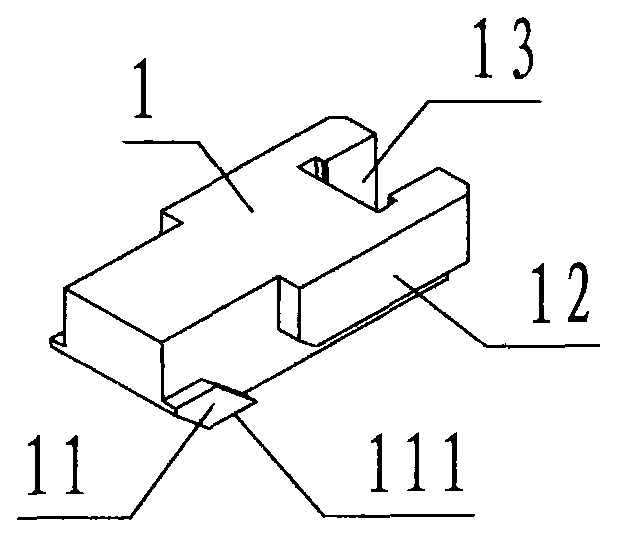
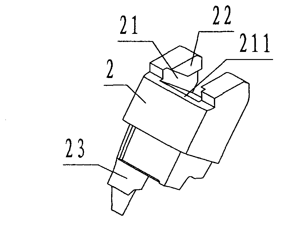
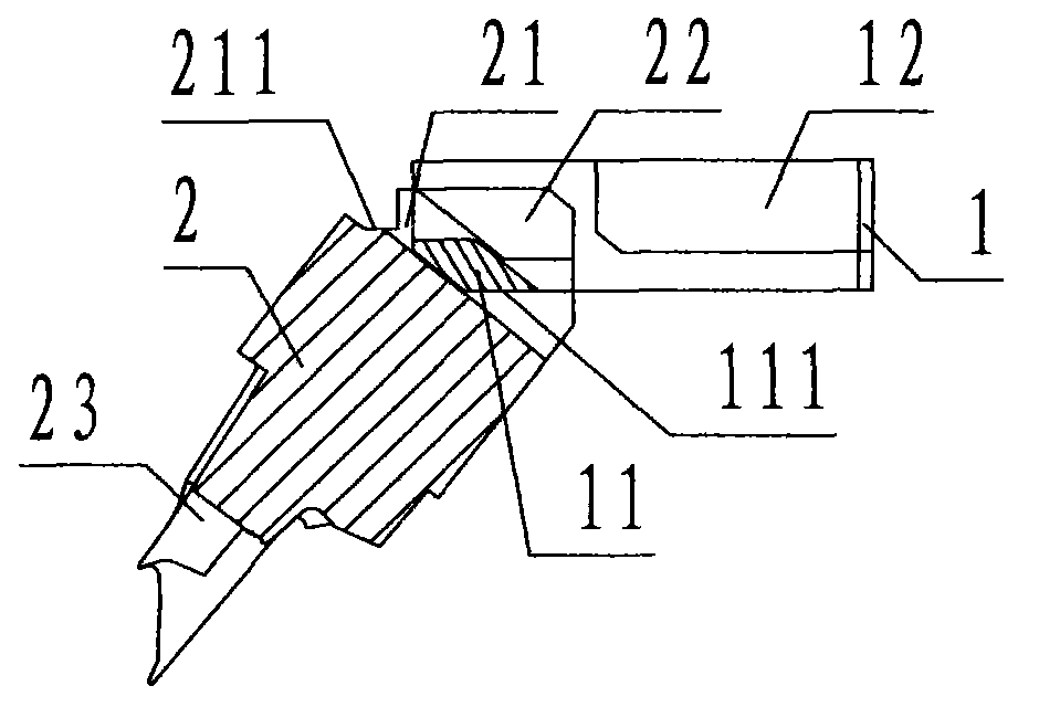
[0025] refer to Figure 1 to Figure 7 , a slanted rail pair with a self-locking plane of the present invention, including a driving slider 1 and a driven slider 2, wherein: the driving slider 1 is a rectangular block-shaped steel member, and the driving slider The front and rear sides of the block 1 are symmetrically provided with protruding inclined slide rails 11 and guide shoulders 12, wherein the front view projection of the inclined slide rails 11 is a parallelogram whose hypotenuse slopes downward from left to right, and the inclined slide rails 11 are located on the active The bottom of the front and rear sides of the left part of the slider 1, the lower left side of the active slider 1 is provided with an inclined surface that is flush with the left inclined surface of the inclined slide rail 11, and the bottom of the inclined slide rail 11 is called the collision plane 111; the guide shoulder 12 The front view projection is rectangular, the guide shoulder 12 is locate...


PUM


Abstract

The invention discloses an inclined sliding groove rail pair with a self-locking flat surface. The inclined sliding groove rail pair comprises a driving sliding block (1) and a driven sliding block (2). By means of the groove rail pair composed of the driving sliding block and the driven sliding block, an abutting flat surface is arranged at the position of an inclined sliding rail of the driving sliding block, a non-return flat surface is arranged at the position of an inclined sliding groove of the driven sliding block, during working, the driving sliding block linearly slides, the inclined sliding rail of the driving sliding block tract pulls the inclined sliding groove of the driven sliding block to enable the driven sliding block to slide in an inclined mode, the abutting flat surface of the driving sliding block slips into and abuts against the upper portion of the non-return flat surface of the driven sliding block so as to prevent the driven sliding block from retracting, so that an inclined core drawing block at the lower end of the driven sliding block is locked, the driving sliding block only slides for one time to perform inclined pulling and locking to the driven sliding block, defects of complicated structures, high costs, excessive hidden danger and fault links and low efficiency which exist in prior art are overcome, and purposes of simplifying structures, reducing costs and fault links and improving efficiency are achieved.

Description

technical field [0001] The invention relates to a groove rail pairing device, in particular to an inclined sliding groove rail pair provided with a self-locking plane, which is used by an injection mold to drive an oblique core-pulling block to be pulled out and demoulded. Background technique [0002] The groove rail pair is composed of a slider with a chute and a slider with a slide rail through sliding buckle connection, and is used to carry the sliding device of the internal parts of the injection mold; the groove rail pair is divided into straight sliding groove rail pair and oblique There are two types of chute rail pairs. The straight chute rail pair is equipped with a straight chute and slide rail. It is usually used for the foot of the inclined ejector pin of the injection mold, and the bearing inclined ejector bar slides laterally with the ejection or reset of the top plate , the inclined chute rail pair is provided with oblique chute and slide rail, the active sli...

Claims


Application Information

Patent Timeline
Patent Type & Authority Applications(China)
IPC IPC(8): B29C45/33B29C45/40
Inventor 文黎清林辉方永杰
Owner NINGBO FANGZHENG TOOL
Why Eureka
Try Eureka