Wire spool and cabinet

A cable tray and cabinet technology, which can be used in the installation of chassis/cabinet/drawer parts, data centers, and support structures, etc., which can solve the problems of messy cabinets and affecting heat dissipation.

Inactive Publication Date: 2013-03-06
HONG FU JIN PRECISION IND (SHENZHEN) CO LTD +1
View PDF3 Cites 5 Cited by
  • Summary
  • Abstract
  • Description
  • Claims
  • Application Information

AI Technical Summary

Problems solved by technology

However, there are many servers and switches in a general server cabinet, correspondingly need to use a lot of cables, these cables make the inside of the cabinet messy, and also affect heat dissipation

Method used


Image

  • Wire spool and cabinet
  • Wire spool and cabinet
  • Wire spool and cabinet

Examples


Embodiment Construction

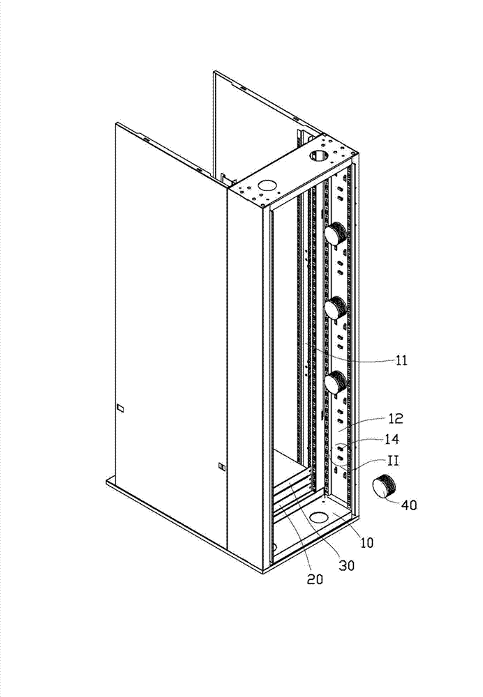
[0014] Please refer to figure 1 and figure 2 A preferred embodiment of the cabinet 10 of the present invention includes several wire trays 40 for accommodating several cables (not shown) connected to the server 20 and the switch 30 in the cabinet 10 .

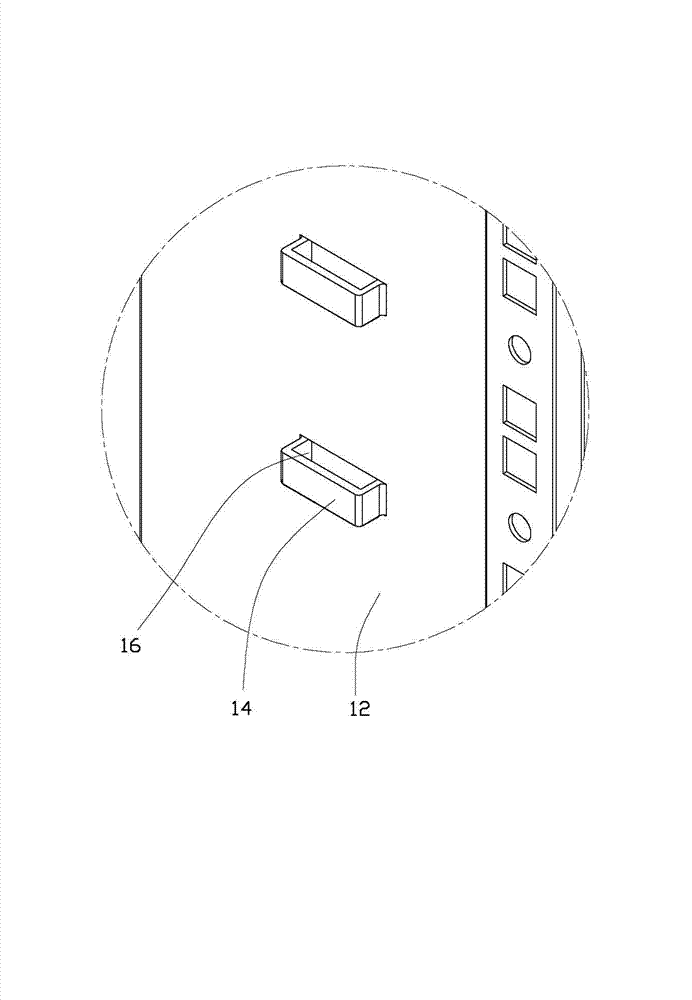
[0015] A rack 11 is installed in the cabinet 10 for accommodating the server 20 and the switch 30 . The inner side of the side wall 12 of the cabinet 10 is longitudinally protruded from the front side or rear side of the frame 11 with several pairs of respectively arched baffles 14, and each baffle 14 and the side wall 12 enclose a socket. 16.

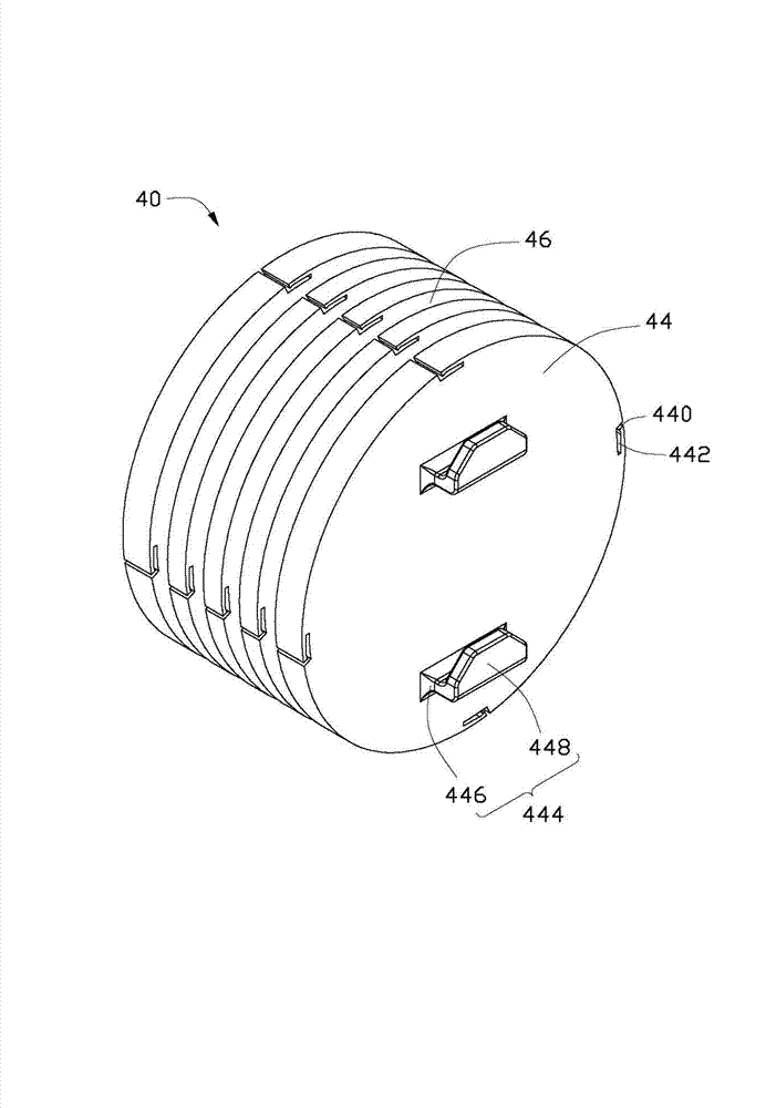
[0016] Please refer to image 3 and Figure 4 , each reel 40 is cylindrical, including a cylindrical winding shaft 42 and a plurality of parallel circular baffles 44 extending outward from the circumferential surface of the winding shaft 42 . An annular receiving groove 46 is formed between every two adjacent baffles 44 . Each baffle plate 44 offers a plurality of openings 440 th...


PUM


Abstract

A wire spool comprises a plurality of retaining plates arranged at intervals. Each two retaining plates form an annular containing groove, and two clamping hooks are protrudingly arranged on the outer side of each outer retaining plate. The invention further provides a cabinet with the wire spool. A plurality of strands of wires and cables can be conveniently and respectively contained in the multiple containing grooves of the wire spool, so that the cabinet can be in good order.

Description

technical field [0001] The invention relates to a wire reel and a cabinet equipped with the wire reel. Background technique [0002] In a server cabinet, cables are usually used to connect servers and switches. However, there are a large number of servers and switches in a general server cabinet, correspondingly requiring a lot of cables, which make the interior of the cabinet messy and also affect heat dissipation. Contents of the invention [0003] In view of the above, it is necessary to provide a wire reel for conveniently arranging cables and a cabinet equipped with the wire reel. [0004] A wire reel includes several baffles arranged at intervals, an annular receiving groove is formed between each two baffles, and two hooks protrude from the outer side of one of the baffles. [0005] A cabinet includes a side wall and a wire reel installed in the side wall, the wire reel includes several baffles, and an annular receiving groove is formed between every two baffles. ...

Claims


Application Information

Patent Timeline
Patent Type & Authority Applications(China)
IPC IPC(8): B65H75/18H05K5/02
CPCB65H75/446B65H2701/34B65H75/4473H05K7/1491
Inventor 梁安刚吴弘毅
Owner HONG FU JIN PRECISION IND (SHENZHEN) CO LTD
Why Eureka
Try Eureka