Composite waste oil filtering equipment

An oil filtration and composite technology, applied in the direction of filtration separation, filtration loop, separation method, etc., can solve the problems of increased production cost, insufficient compact structure, affecting performance, etc., to achieve cost savings, high synchronous work efficiency, and easy maintenance. maintenance effect

Active Publication Date: 2021-05-07
唐山浩昌杰环保科技发展有限公司
View PDF8 Cites 0 Cited by
  • Summary
  • Abstract
  • Description
  • Claims
  • Application Information

AI Technical Summary

Problems solved by technology

[0002] In modern industrial production, it is necessary to use a variety of oil products to assist equipment production, such as hydraulic oil, gear oil, engine oil, lubricating oil, etc. After these oil products are used for a long time, they are often mixed with many solid particles , iron filings, impurities and water become waste oil, which seriously affects the performance. If it is not replaced for a long time, it may cause equipment damage. However, regular replacement of oil products will lead to a substantial increase in production costs. Therefore, modern industries generally use filters to filter Waste oil recycling, so based on the consideration of environmental protection and cost saving, a filter equipment with both solid-liquid separation function and oil-water separation function is needed
[0003] Disclosed in CN111995153A is a patent called "a kind of environmental protection equipment for domestic sewage treatment", which discloses the equipment housing, the shunt filter screen, and the waste residue storage box. Its disadvantages are: 1. Its structure is not compact enough and takes up space Large, too many motor settings, can not achieve synchronous work of various components, low efficiency; 2. It uses a filter to filter solid impurities, the filter is used as a consumable, the cost is high

Method used


Image

  • Composite waste oil filtering equipment
  • Composite waste oil filtering equipment
  • Composite waste oil filtering equipment

Examples


Embodiment Construction

[0047] The present invention will be further described below in conjunction with drawings and embodiments.

[0048] In the description of the embodiments of the present invention, it should be noted that the terms "center", "longitudinal", "transverse", "upper", "lower", "front", "rear", "left", "right" , "vertical", "horizontal", "top", "bottom", "inner", "outer" and other indicated orientations or positional relationships are based on the orientations or positional relationships shown in the drawings, and are only for the convenience of describing this The embodiments and simplified descriptions of the invention do not indicate or imply that the devices or elements referred to must have a specific orientation, be constructed and operate in a specific orientation, and therefore should not be construed as limiting the embodiments of the present invention. In addition, the terms "first", "second", and "third" are used for descriptive purposes only, and should not be construed a...


PUM


Abstract

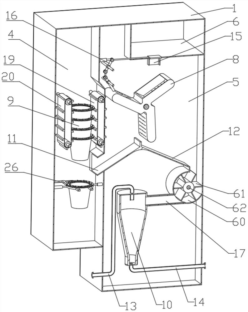
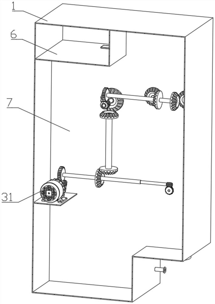
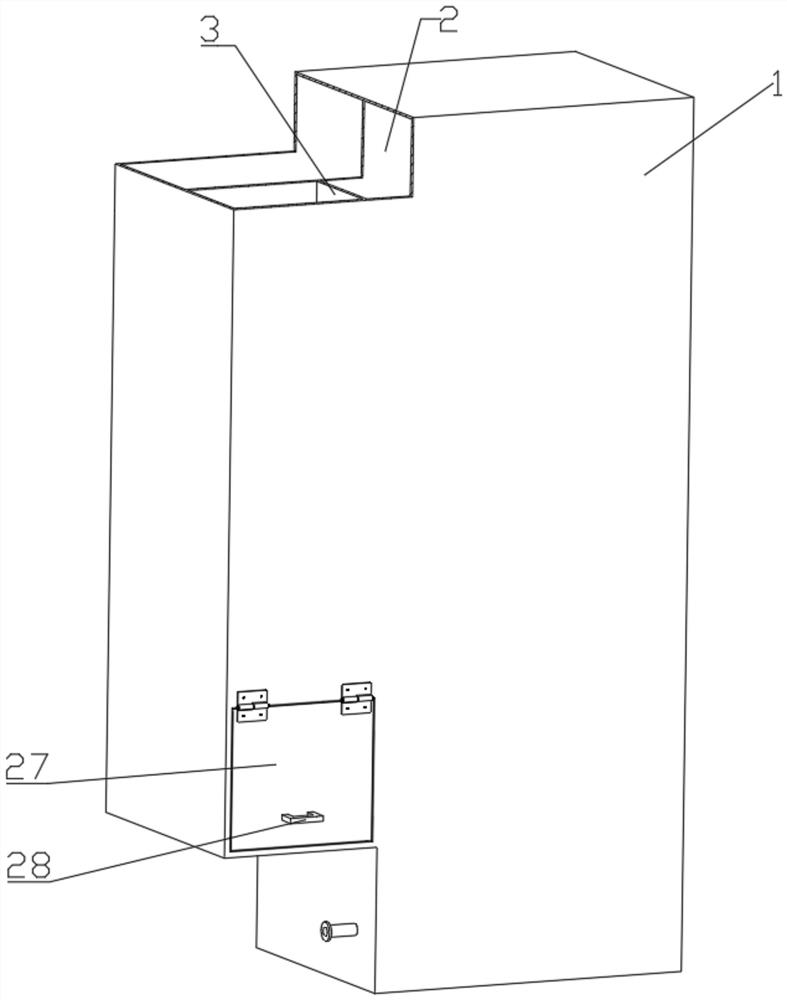
Composite waste oil filtering equipment comprises an oil storage tank and a shell, a first partition plate for dividing the shell into a front shell and a rear shell is arranged in the shell, the interior of the front shell is divided into an oil residue storage shell and a filtering shell through a second partition plate, and an oil residue separation rotor, an oil residue separation guide plate and an oil-water separator are arranged in the filtering shell; and an intermittent valve unit controlled by the rotating speed of the oil residue separation rotor is arranged at the communicating position of the filtering shell and the oil storage tank, a conveying belt and a clamping ring which work synchronously are arranged in the oil residue storage shell, and a transmission unit is arranged on the rear shell. The composite waste oil filtering equipment is compact in structure, all components work synchronously, efficiency can be remarkably improved, and the composite waste oil filtering equipment is totally closed in the filtering process and free of peculiar smell drifting.

Description

technical field [0001] The invention relates to the field of waste oil filtration, in particular to a composite waste oil filtration device. Background technique [0002] In modern industrial production, it is necessary to use a variety of oil products to assist equipment production, such as hydraulic oil, gear oil, engine oil, lubricating oil, etc. After these oil products are used for a long time, they are often mixed with many solid particles , iron filings, impurities and water become waste oil, which seriously affects the performance. If it is not replaced for a long time, it may cause equipment damage. However, regular replacement of oil products will lead to a substantial increase in production costs. Therefore, modern industries generally use filters to filter Waste oil recycling, so based on the consideration of environmental protection and cost saving, a filter equipment with both solid-liquid separation function and oil-water separation function is needed. [000...

Claims


Application Information

Patent Timeline
IPC IPC(8): B01D36/00
CPCB01D36/008
Inventor 苟荀
Owner 唐山浩昌杰环保科技发展有限公司
Why Eureka
Try Eureka