
Gasification of carbonaceous material

A carbonaceous material, gasifier technology, applied in fixed bed gasification, mechanical details of gasification devices, combustion methods, etc., can solve problems such as poor alignment, functional failure of grid components, unsuitable biomass gasification, etc.

Inactive Publication Date: 2013-03-06
SASOL TEKHNOLODZHI PROPRIEHJTEHRI LTD
View PDF6 Cites 6 Cited by
  • Summary
  • Abstract
  • Description
  • Claims
  • Application Information

AI Technical Summary

Problems solved by technology

[0012] WO 2006 / 061738 attempts to overcome the problems of agglomeration of the particulate coal feedstock fed to a fixed bed coal gasifier, which leads to unstable operation of the gasifier, and heterogeneous coal formation due to preferential gas flow through the aforementioned Problems with "hot spots" caused by beds
Nowhere in WO 2006 / 061738 is there any mention of the problems of misalignment between the upper and lower grid members, relative rotation of the upper and lower grid members about the keyed torque transfer device, or Grille assembly malfunction due to shearing of connecting bolts between upper and lower grille members
CN 201762288 identifies a number of problems associated with prior art grates including, inter alia: (i) ash buildup on the grate resulting in inefficiency in the gasifier, (ii) ash clogging the grate holes, thereby preventing combustible gases from leaving the furnace body through the holes, thereby inhibiting gas production, (iii) the holes in the grate lead to material leakage, and (iv) because the holes in different types of grates are different in size to suit different The gasification of various types of biomass, so the existing grid is not suitable for the gasification of various types of biomass

Method used


Image

  • Gasification of carbonaceous material
  • Gasification of carbonaceous material
  • Gasification of carbonaceous material

Examples


Embodiment Construction

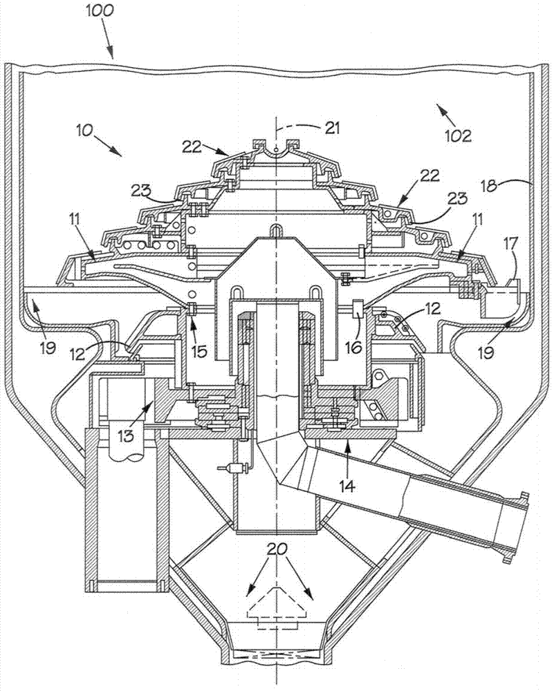
[0039] refer to the attached figure 1 , the reference numeral 10 generally refers to a grid assembly according to the present invention, which is installed in a gasification vessel 100 of a fixed bed dry bottom coal gasifier according to the present invention. The gasification vessel 100 defines a gasification chamber 102 within which the grid assembly 10 is located. The gasification chamber 102 has walls 18 .

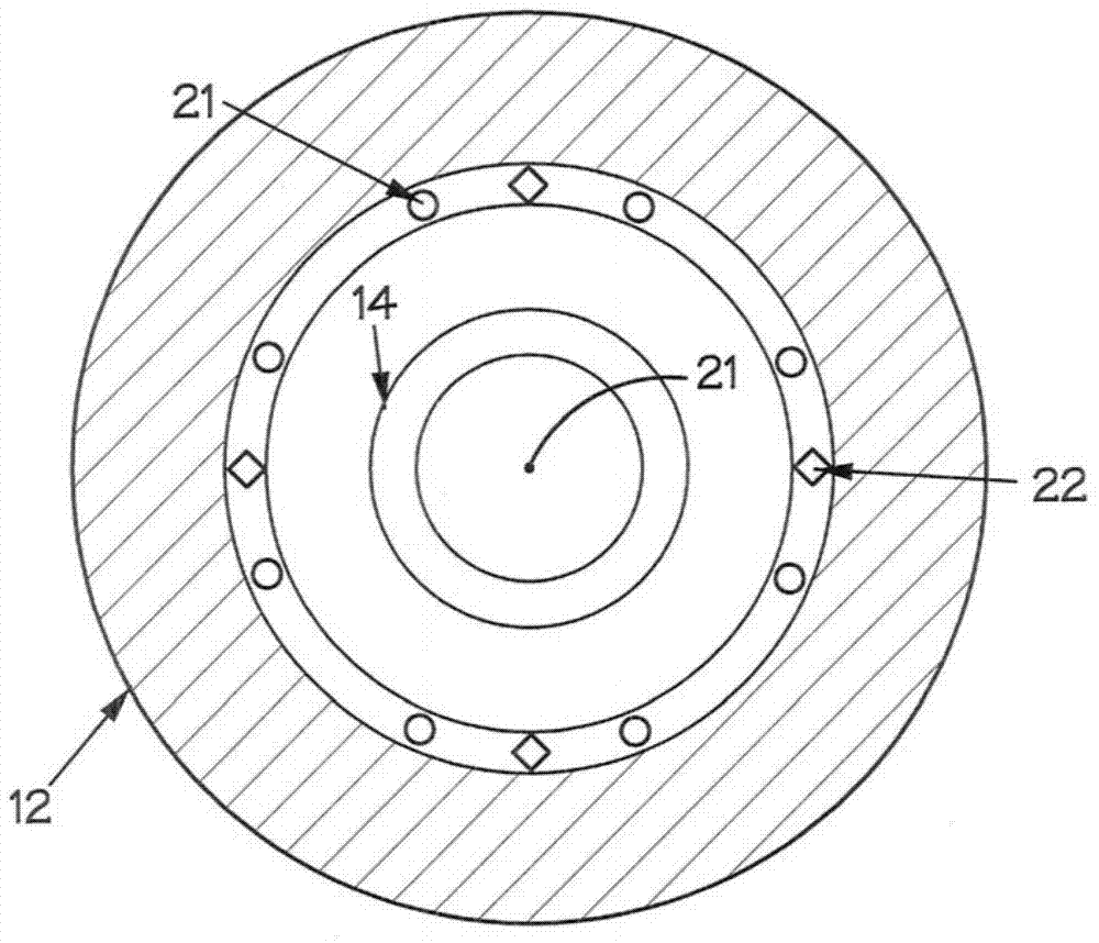
[0040] The grill assembly 10 includes an upper rotatable grill member 11 that is fixedly connected to the lower rotatable support structure 12 using a plurality of connecting bolts 15 and at least two keyed torque transmitting devices 16 . The lower rotatable support structure 12 is drivingly connected to a ring gear 13 which is connected via a gearbox to an electric motor (not shown). In use, the electric motor and gearbox are used to rotate the rotatable members 11 , 12 , 13 of the grille assembly 10 .

[0041] The rotatable members 11 , 12 , 13 are supported by ...


PUM


Abstract

The present invention relates to GASIFICATION OF a CARBONACEOUS MATERIAL, and discloses a grate assembly 10 for a gasifier for gasifying carbonaceous material producing ash includes an upper rotatable grate component 11 and a lower rotatable support structure 12 fastened to the upper rotatable grate component by a plurality of removable fasteners 15 acting to prevent vertical displacement of the upper rotatable grate component and the lower rotatable support structure. The lower rotatable support structure is configured to be drivingly rotated about a common vertical axis of rotation 21 shared with the upper rotatable grate component. The assembly 10 further includes at least two key torque transmitters 16 spaced angularly relative to the common axis of rotation and engaging the upper rotatable grate component and the lower rotatable support structure to transfer torque from the lower rotatable support structure to the upper rotatable grate component when the lower rotatable support structure is driven.

Description

technical field [0001] The present invention relates to the gasification of carbonaceous materials. In particular, the present invention relates to a grid assembly of a gasifier for gasifying carbonaceous materials and to a gasifier for gasifying carbonaceous materials. Background technique [0002] For some gasifiers such as FBDB TM Gasifiers, etc., require intermittent or continuous loading and unloading of particulate materials, such as particulate carbonaceous materials (eg, coal), ash, and the like. Thus, for example, in the case of a pressurized gasifier (eg, a fixed bed dry bottom gasifier), particulate carbonaceous feedstock, such as coal, is loaded into the gasification chamber of the gasifier to form a bed (in the case of a fixed bed gasifier), and gasification is carried out at high temperature and pressure, after gasification, any remaining ungasified material passes through the rotatable grill assembly and ash lock as ash ) is removed from the gasifier. ...

Claims


Application Information

Patent Timeline
IPC IPC(8): C10J3/42
CPCF23H9/00C10J2200/09F23H9/02C10J3/42F23H17/08F23H2700/009F23H2700/005
Inventor 保罗·斯米特·鲍曼丹尼尔·弗朗西斯
Owner SASOL TEKHNOLODZHI PROPRIEHJTEHRI LTD
Learn More