Energy efficiency Ethernet with low power active idle transmission mode

A technology of transmission mode and idle mode, applied in the field of energy-efficient Ethernet, which can solve problems such as difficulty in identifying low link utilization periods and reduced energy-saving potential

Active Publication Date: 2013-03-13
AVAGO TECH INT SALES PTE LTD
View PDF5 Cites 5 Cited by
  • Summary
  • Abstract
  • Description
  • Claims
  • Application Information

AI Technical Summary

Problems solved by technology

Here, the identification of periods of low link utilization is more difficult and the energy saving potential is reduced

Method used


Image

  • Energy efficiency Ethernet with low power active idle transmission mode
  • Energy efficiency Ethernet with low power active idle transmission mode
  • Energy efficiency Ethernet with low power active idle transmission mode

Examples


Embodiment Construction

[0027] Various embodiments of the invention are discussed in detail below. While specific implementations are discussed, it should be understood that this is done for illustration purposes only. A person skilled in the relevant art will recognize that other components and configurations may be used without departing from the spirit and scope of the invention.

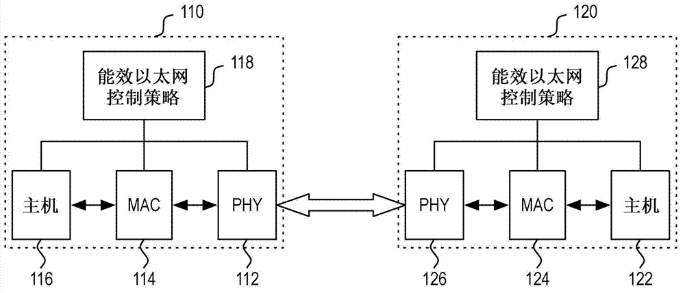
[0028] Energy Efficient Ethernet networks attempt to conserve energy when the network's traffic utilization is not at its maximum capacity. This is used to minimize performance impact while maximizing power savings. At a broad level, energy efficiency control policies for specific links in the network determine when to enter an energy-saving state, what energy-saving state (i.e., energy-saving level) to enter, how long to stay in this energy-saving state, transition from the previous energy-saving state Why energy-saving state and so on. In one embodiment, an energy efficiency control policy may base these energy sav...


PUM


Abstract

Energy efficient Ethernet with a low power active idle transmission mode. A low power active idle transmission mode is defined for the transmission of idle signals during inter-packet gaps. The low power active idle transmission mode can provide energy savings in those instances that preclude the use of a low power idle mode and / or subrating to produce greater energy savings.

Description

technical field [0001] The present invention relates generally to energy efficient Ethernet networks, and more particularly to energy efficient Ethernet with a low power active idle transmission mode. Background technique [0002] Energy costs have continued to rise at an accelerated rate in recent years. In this context, various industries have become increasingly sensitive to these rising costs. One area that has drawn increasing attention is IT infrastructure. Many companies are currently reviewing the power usage of their IT systems to determine if they can reduce energy costs. To this end, an industry has emerged focused on energy efficient networking to address the rising cost of IT equipment usage in aggregate (ie, PCs, displays, printers, servers, network equipment, etc.). [0003] One aspect to consider in designing energy efficient solutions is the utilization of network links. For example, many network links are often idle between occasional bursts of data. D...

Claims


Application Information

Patent Timeline
Patent Type & Authority Applications(China)
IPC IPC(8): H04L12/12H04L12/10H04L12/28
CPCH04L12/40039Y02B60/32Y02B60/35H04L12/12H04L12/10Y02B60/126Y02B60/34G06F1/3278Y02D10/00Y02D30/00Y02D30/50H04L65/00
Inventor 瓦埃勒·威廉·迪亚卜穆罕默德·泰兹贝斯科特·鲍威尔
Owner AVAGO TECH INT SALES PTE LTD
Why Eureka
Try Eureka